Many of the structures available in MIKE 11 requires a Structure Geometry definition to complete the structure input.
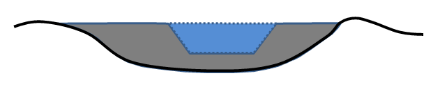
It is important to notice, that the Structure Geometry to be defined is actually the geometry - or level-width relation - of the sections of the hydraulic structure where the water can potentially flow. That is, the Flow Area definition as illustrated in Figure 2.47 marked with the dashed (blue) section.
Figure 2.47 Illustration of Structure Geometry definition. The Dashed (blue) area which potentially conveys water over/through the structure is the geometry which must be defined
Example: Assuming the following geometrical definition of the dashed (blue) flow area in Figure 2.47: Crest level of structure is at level 3 m (crest level = bottom of blue area in figure), bottom width is 5 m, top-width is 7 m at a level of 5 m. A structure geometry definition in this case is normally defined as presented in Table 2.1 below
|
Level [m] |
Width [m] |
|---|---|
|
3.00 |
0.00 |
|
3.05 |
5.00 |
|
5.00 |
7.00 |
:
![]()