Most hydraulic structures available within MIKE 11 can be defined as one of three different types; ‘Regular’, ‘Side Structure’ or ‘Side structure with Reservoir’. Structures without this option works as regular structure.
Regular
Regular structures are internal structures that specify a flow in the river branch typically based on up- and down- stream water level conditions.
Side Structure
Side structures are special type of a regular structure. Side structures extract water from the river network at the location where the side structure is defined.
Internally in the calculation engine, side structures are handled through an automatic generation of an ‘artificial’ side branch with the side structure included as a regular structure placed midway in the side branch as illustrated in Figure 2.44.
Specific characteristics of a Side Structure include:
· Head losses are excluded from the flow calculation for side structures by setting internally the flow areas of the cross sections in the side structure branch as extremely large (1e20 m2) and hence, the velocity component in these sections (V=Q/A) is a negligible number.
· For culverts and weirs, an assumption of free out- and over-flow respectively is implemented through an internally defined water level boundary condition for the outflow point of the artificial side structure branch. The boundary condition is defined as a water level boundary with a low water level.
· The naming convention used for the artificial side branch is:
"SS_"<original branch name>"_"<original chainage>
· In case of multiple side structures defined at the same location, these will all be included in the same side branch as a ‘composite side structure’.
· A side structure branch is a h-Q-h branch with two cross section h-points in each end of the branch and a structure in the centre Q-point.
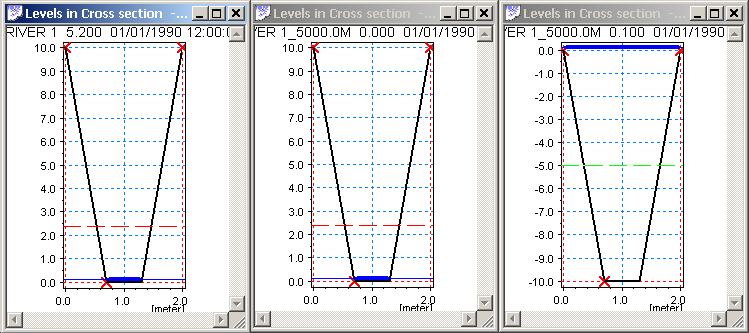
Up- and downstream cross sections in the Side Structure Branch are automatically assigned with a shape identical to the main river cross section located immediately downstream of the side structure location. Upstream cross section of the Side Structure branch is identical to the section in the main river, but the downstream section has been shifted 10 m down in order to obtain a free outflow condition in the Side Structure. See Figure 2.43.
Figure 2.43 Cross sections as defined in the artificial Side Structure branch. Left part illustrates the cross section in the main river downstream of the chainage defining the side structure. Middle part illustrates the upstream cross section at chainage 0 of the side structure branch (=copy of main branch section) and right part illustrates the downstream cross section of the Side Structure Branch, which is identical in shape as the other sections but shifted by -10 m
An example of a Side Structure branch is illustrated in Figure 2.44:
Side Structure included in "RIVER 1" at chainage 5000 meter will effectively be placed in "SS_RIVER 1_5000.0M" in chainage 50 meter. The side branch, "SS_RIVER 1_5000.0M", will have a length of 100 meter.
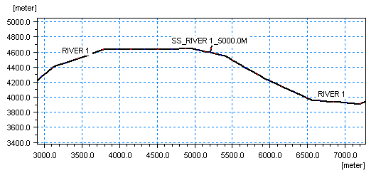
Figure 2.44 Illustration of automatically generated Side structure branch
Inclusion of Side Structures with Reservoir in a branch results in an automatic generation of a side branch with the structure placed midway as described for Side Structures without reservoirs.
The downstream cross section of the side structure branch has a user-defined, additional storage area assigned, which assigns the reservoir data specified as a level dependent additional storage function (ref. Section 3.2.2 Processed data, Tabular View) defined in the downstream (outflow) h-point of the side structure branch. The significant difference between a structure defined as ‘Side Structure’ and ‘Side Structure with Reservoir’ is therefore, that in the latter case, the water conveyed through the side structure is stored in the system and can be analysed, whereas for the structure type without the Reservoir, the water simply leaves the river model and disappears completely.
The Additional Storage relation is defined through the dialog opened when pressing the  button (Figure 2.45):
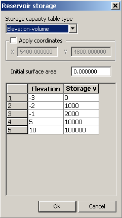
Figure 2.45 Dialog for specifying Additional storage for Side Structures with Reservoir
Two options for defining the Reservoir storage exist:
· Elevation-area
The Elevation-Area relation specified in the table is used directly as the additional storage area as a function of the water level in the reservoir.
· Elevation-volume
Additional storage area is derived from the Elevation-Storage relation following the relation:
(2.1) 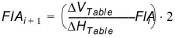
where:
FlAi : Flooded or additional storage Area at level ‘i’
 VTable and
  HTable are differences in Volumes and Levels respectively between values defined in the Storage-elevation table
Additional specific features of the Side Structure with Reservoir:
· Head losses are excluded from the flow calculation for side structures with Reservoir by setting internally the flow areas of the cross sections in the side structure branch as extremely large (1e20 m2) and hence, the velocity component in these sections (V=Q/A) is negligible.
· The boundary introduced through the inclusion of the side weir is internally specified as a no flow boundary. Flow may be included through specification of point source boundaries at the boundary.
· More side structures with reservoir in the same location will result in one side branch for each.
· The side branches will be named with the naming convention:
"SSPR"<original branch name>"_"<original chainage>"_"<Structure ID>.
· ‘Apply Coordinates’. The Apply coordinates offers a possibility for defining coordinates for the reservoir - which in the case of the artificially generated side structure branch is identical to the end point of the side structure branch. Hence, the coordinates defines the appearance of the side structure branch and a length of the branch will be calculated according to the specified coordinates.
· The cross sections applied in the artificially generated Side Structure Branch with Reservoir are defined such that the upstream cross section is a copy of the section in the main river downstream of the chainage defining the side structure and the downstream cross section is a defined as a triangular cross section shape as illustrated in Figure 2.46.
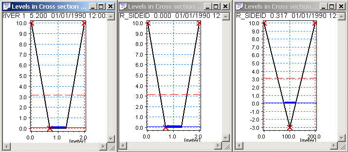
Figure 2.46 Cross sections as defined in the artificial Side Structure with Reservoir branch. Left section illustrates cross section in main river downstream of chainage defined for Side Structure. Middle section illustrates the upstream section of the side structure branch (copy of main branch section) and right section illustrates triangular section applied at downstream h-point of Side Structure Branch
Levels of the cross section is adapted from the defined Level-Area/Volume table, whereas the widths (0 m at bottom and 100 m in top of section are just artificial numbers applied in order to draw a cross section in the results presentation tools. The calculated storage volume of the section is defined from the table-values.
An example of a Side Structure with Reservoir definition: Side Structure included in "Branch1" at chainage 1000 meter with ID SideWeir1 will effectively be placed midway in branch "SSPR_Branch1_1000m_SideWeir1". The length of side branch, "SSPR_Branch1_1000m_SideWeir1", will follow from the position specified if any, otherwise it will be 100 metres.
![]()