
The ‘Edit Link Channel Parameters...’ button
This button is only enabled when a branch has been defined with the branch type of ‘link channel’.
Link Channels - what are they?
The link channel is a short branch used to connect a flood plain to the main river branch and therefore typically represents the embankment geometry between parallel rivers (e.g. main river branch and flood plain branch). Link channels do not require cross sections to be specified and are consequently simpler to use than regular channels. The link is modelled as a single structure branch of only three computation calculation points (h-Q-h). The Q-point in the link channel branch is defined through an ‘open culvert’ type of structure. That is, an overflow weir with a length to include the friction loss component.
Note: Following the internal formulation of the link channel where no true cross sections are defined in a link channel branch, the usage is restricted to Hydro-Dynamic simulations ONLY. Thus, for Advection-Dispersion, Water-Quality and Sediment-Transport calculations the set-up should be void of link channels and instead connecting branches between main rivers should be defined out of ‘regular’ branches with cross sections defined and eventual a weir included to describe embankment levels if this is what should be represented with the connecting branch.
The link channel dialog is used for specifying all parameters appropriate for the link channel e.g. geometry, head loss coefficients etc.
Typical Link channels representation are illustrated in Figure 2.36.
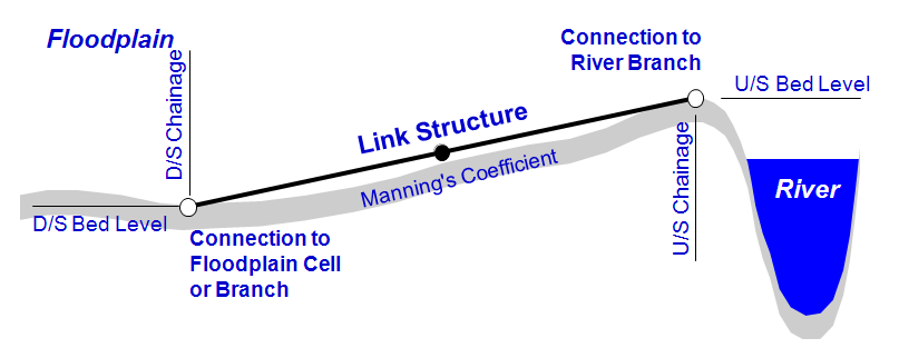
Figure 2.36 Longitudinal parameters and representation of a Link Channel
Geometry
The link-channel geometry comprises typically the definition of a longitudinal geometry of the embankment along the river. The geometry is defined from the following parameters:
· Bed Level US:
Upstream bed level of the link channel.
· Bed Level DS:
Downstream bed level of the link channel.
· Additional Storage:
Link channels do not contain cross sections and do not contribute to the storage capacity at nodal points where the link connects to a main branch. The Additional Storage parameter can be used to avoid zero storage at nodal points to which only link channels and no regular channels are connected.
The Additional Storage combo-box defines whether additional storage is to be added at the upstream, downstream or both ends of the link channel. The actual storage is specified in the additional flooded area column of the processed data in a cross section defined at the same location as the link channel.
Bed resistance
The bed resistance along the length of a link channel can be described using Manning's M or Manning's n.
Head Loss Coefficients
All four factors are dimension less and must be within the range 0.00 - 1.00.
Cross Section Geometry
A depth-width table defines the cross section geometry of the flow area in a link channel. Both the depth and the width must be increasing.
Q/h - relations
Free outflow Q/h-relation must be calculated prior to calculation. To calculate the Q/h relationship, specify the number of relationships required and press the Calculate button. The result of the calculation will appear in the table. If any of the parameters defining the link channel geometry, or loss coefficients are changed the Q/h relations must be re-calculated.
Table values in the Q/H relations can be changed if required but general recommendation is to leave the table as is from the automatic calculation when pressing the Calculated button. Only the columns ‘US Type’ and ‘DS Type’ can not be changed. These are only indicators of flow type derived from the calculated flow parameters in the link channel and the values of these columns are not included in the calculations.
Table parameters are:
y: water depth in link channel structure
A: Flow Area in link channel structure
R: Hydraulic Radius in link channel structure
C: Conveyance indicator in link channel structure
Qc: Critical flow in link channel structure
Hus: Water level in h-point upstream of link channel structure
Hds: Water level in h-point downstream of link channel structure
![]()