The outer boundary conditions are defined as line segments between two boundary points. The boundary points are, in principle, independent of the model domain because they do not need to lie on the model boundary. Rather they are projected onto the nearest model boundary cell. Thus, the model boundary can be modified slightly without having to modify the boundary locations. However, if the model boundary is moved significantly or if the boundary is convoluted then the calculated ‘nearest’ node might not be the one expected.
Specifying a boundary condition
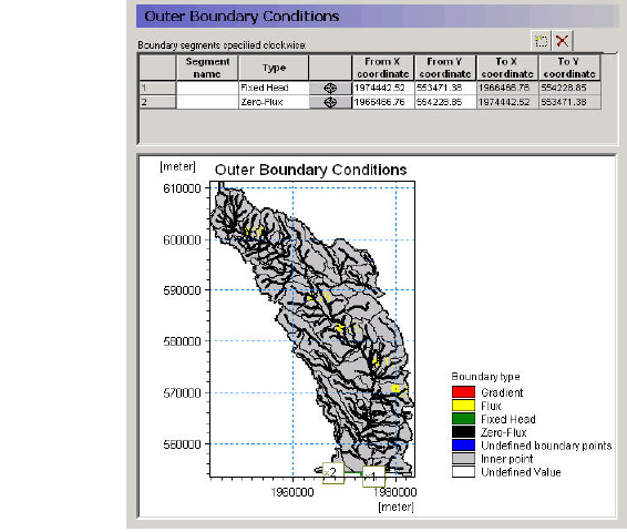
To specify an outer boundary segment,
1. add a new line to the outer boundary points table
2. click on the target icon,
3. click on one end of your boundary segment,
4. add a second line to the outer boundary points table
5. click on the new target icon,
6. click on the other end of your boundary segment
7. Change the name of the top line of the points table,
8. Select the appropriate boundary condition for the boundary segment.
Fixed Head - This boundary prescribes a head in the boundary cell. The head can be fixed at a prescribed value, fixed at the initial value from the initial conditions, or assigned to a .dfs0 time series file. If a time series input is used, then the actual value used in the model at the current time step is linearly interpolated from the available values.
The last option is a time varying dfs2 file, which is typically extracted from a regional results file. This can be done using the MIKE Zero Toolbox Extraction tool: 2D Grid from 3D files. MIKE SHE then interpolates in both time and space from the .dfs2 file to the local head boundary at each local time step.
Zero flux - This is a no-flow boundary, which is the default.
Flux - This boundary describes a constant or time varying flux across the outer boundary of the model. A time varying flux can be specified as a mean step-accumulated discharge (e.g. m3/s) or as a step-accumulated volume (e.g. m3). A positive value implies an inflow to the model cells.
Gradient - This boundary describes a constant or time varying gradient between the node on the outer boundary and the first internal node. A time varying gradient can be specified as an instantaneous dimensionless or percent value. A positive gradient implies a flux into the model.
Notes
1. The head is calculated in a No Flow outer boundary cells, whereas the head is specified in the Fixed Head outer boundary cells, but in both cases all properties must be assigned to all outer boundary cells.
2. An internal model cell in contact with multiple boundary cells will not receive multiple quantities of water.
3. Additional detailed information can be found under Boundary Conditions (V1 p. 583) in the Saturated Flow - Technical Reference (V1 p. 573).
4. An error will be generated if the flux/gradient input cell
· has zero thickness,
· has a horizontal hydraulic conductivity of zero,
· is an inactive internal boundary cell, or
· is a fixed head internal boundary cell.
5. A warning will be issued if the flux/gradient boundary
· is a head controlled flux (GHB) internal boundary cell, or
· is a fixed head drain internal boundary cell.
Related Items:
· Saturated Flow - Technical Reference (V1 p. 573)
· Boundary Conditions (V1 p. 583)
![]()