Catchments are generally included in a model to provide catchment runoff as an inflow to the River network. A model may contain any number of catchments.
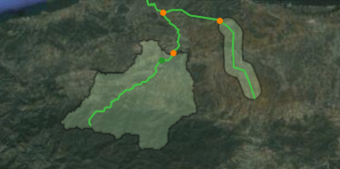
Catchments may be represented schematically, or by their delineated boundaries as illustrated in figure below. The primary difference between schematic and delineated catchments in a model setup is, that the catchment surface area is directly derived from the delineation of catchments whereas the surface area must be specified manually for the schematic catchments.
Figure 7.1 Illustration of catchments in a MIKE HYDRO model
Runoff from catchments are either user-defined through a predefined runoff time series file or it can be calculated using one of several rainfall runoff models available. Runoff from a catchment is added to a river network in catchment nodes.
Additional features and calculation options related to catchments include groundwater and definition of sediment load as input to a reservoir sedimentation calculation.
There are several ways of creating catchments, each of them being related to a specific Add button under the Catchments ribbon in Map view.
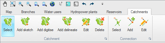
Figure 7.2 Catchment ribbon in Map view
MIKE HYDRO offer multiple options for catchments definitions
· Sketched Catchments are created by selecting the ‘Add sketch’ button and clicking on the branch at the downstream end of a catchment. Here a catchment node will be automatically inserted. The upstream end of a catchment is given by the next upstream catchment node or the end of the branch.
· Delineated catchments may be created by using a DEM (cf. Section 5.4 (Digital Elevation Model (DEM)). This type of catchment is added by pressing the ‘Add delineate’ button and clicking on the branch at the downstream end of a catchment. The catchment is automatically delineated based on the elevations from the DEM, and a catchment node is automatically inserted.
· Digitized catchments may be drawn on the map using the ‘Add digitize’ button. For this type of catchment, the connection to the branch has to be manually defined with a connection. The catchment connections can be created and edited using the buttons from the Connection group in the ribbon.

Note that a catchment created from the map, regardless of its type (sketched, delineated or digitized), can have its shape corrected from a shape file using the ‘Load shape’ button in the Tabular tab. This however does not change the catchment connection or the catchment node.

Note that delineated catchments starting in a local depression (area with local minimum values) can have an unexpected result as an artificial flow pattern in the lake is used for defining the catchment boundary.
If 'Ctrl'-button is pressed when inserting the catchment outlet the catchment will include both the entire lake and the catchment to the lake.
The ‘Edit’ button from the Catchment group in the ribbon may be used to edit the geometry of a catchment on the map. After selecting this button and clicking on the desired catchment, all the vertices defining the polygon of the catchment become visible.
To move a vertex, click and drag the selected vertex.
To add a new vertex, click on the desired location along the edge of the catchment.
To delete a vertex, double click the selected vertex.

Note that to delete multiple vertices at the same time, zoom out in such a way that these vertices appear almost superimposed. After double clicking, all the vertices in the vicinity of the selected location will be deleted.
To delete a catchment from the map, select the ‘Delete’ button in the Catchment group in the ribbon and click on the desired catchment.
To delete one or more catchments from the Tabular tab, highlight the catchment(s) to be deleted in the overview table and press the ‘Delete’ button above the table.
The three buttons from the Connection group in the ribbon are described below:
Select. This button can be used to select one or more catchment connections. To select multiple connections, press the ‘Ctrl’ key on the keyboard while selecting the items on the map.
Add. Select the ‘Add’ button to connect a catchment to a branch, or to connect it to a new location. After pressing the ‘Add’ button, click on the border of a catchment and drag to the branch. A catchment node is added at the connected location on the branch.
Edit. This button may be used to move the connection to another location. To edit the connection, first click the ‘Edit’ button and click once on the connection, then drag the white symbol to its new location. Click once again to stop editing. When a catchment is connected to a new location on a branch, a new catchment node is added to this branch.
![]()