
You can specify operating rules for supplying water to the individual users. This is done by specifying the No. of Reduction levels. For each Reduction level a time series containing Reduction water levels and corresponding Reduction factors must be specified.
Note that Allocation pool reservoirs have Reduction thresholds (fraction of pool volume) instead of Reduction levels (reservoir water levels). Reduction thresholds are specified in the same way as Reduction levels.
To specify Reduction level time series for a Water user, click on the small arrow to the left of the Water user name. A grid cell then becomes available for each Reduction level.
Click on the grid cell and a  button appears in the right-hand side of the grid cell.
Click on the  button and click Browse... to include an existing time series or click Create a new file… to open the ‘Create a new file’ dialogue. Two items must be specified: Reduction level and Reduction fraction.
When the reservoir water level falls below Reduction level 1 for a specific user, the actual extraction is calculated as the water demand times the specified Reduction factor 1. If the reservoir water level falls below Reduction level 2, a more drastic Reduction factor 2 is applied, and so on. Each user has its own set of reduction levels and corresponding reduction fractions and can have as many sets as required.
Figure 9.5 illustrates how different Reduction levels and factors can apply to different Water users. In the figure, a low priority user (e.g. industrial production) is getting its demand reduced earlier and more drastically, than a high priority water user (e.g. public water supply).
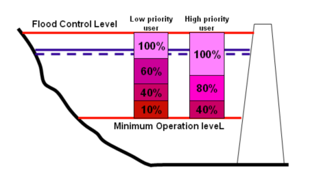
Figure 9.5 Illustration of reduction levels and reduction fractions for two users

Example:
Assuming two Water users extracting water from a Reservoir. The following rules apply for the two water user nodes:
The demand for both Water user nodes is 13.89 m3/sec.Operating policy:
· User node 1 (W4): Reduction level at:541 m, Reduction factor: 0.8
· User node 2 (W6): Reduction level at 540 m, Reduction factor: 0.6
The initial water level in the Reservoir is 544 m, and the inflow is zero until the 20th January, where the inflow is 35 m3/s. Figure 9.6 illustrates how the water level is falling as water is extracted from the Reservoir. When the water level reaches level 541 m, the withdrawal by user node 1 is reduced to 80%, and the water level falls with a lower rate. When the water level falls below level 540 m, the withdrawal to user node 2 is also reduced. Once the inflow to the Reservoir starts the water level is rising with a reduced rate as the withdrawal increases.
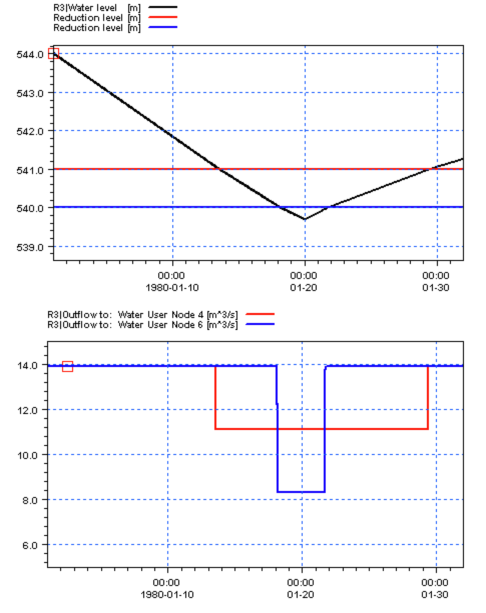
Figure 9.6 Water supply as a function of water level and reduction fractions
![]()