From Release 2019 update 1, MIKE HYDRO Basin will include outlet specifications for all types of reservoirs (Lakes, Rule Curve and Pool Allocation reservoirs). The approach extends MIKE HYDRO Basin's dam reservoir operation capability while maintaining the simplicity of the modelling process.
Reservoir releases during flood control operations can now be controlled by one or more outlets for each connected node. To avoid unnecessary complexity, the number of outlets connected to water users or reservoirs is limited to one.
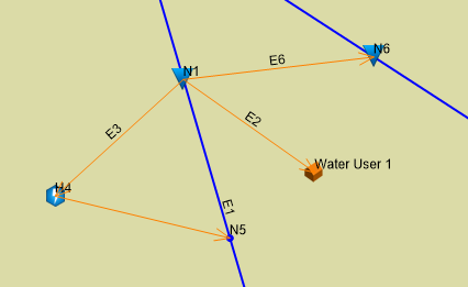
Figure 9.8 illustrates an example, where a reservoir is connected to a water user, a hydro power plant, and a reservoir:
Figure 9.8 Example of connections to reservoir
Outlets connected to different downstream elements in the network seldom have identical capacities and conditions for releasing water. It must therefore be possible to specify individual outlet parameters for each outlet. This will also provide a more realistic water level simulation in response to extreme inflows.
The in previously MIKE HYDRO Basin versions existing spillway tab has been replaced by the 'Outlets'-tab, as illustrated in Figure 9.9 below:
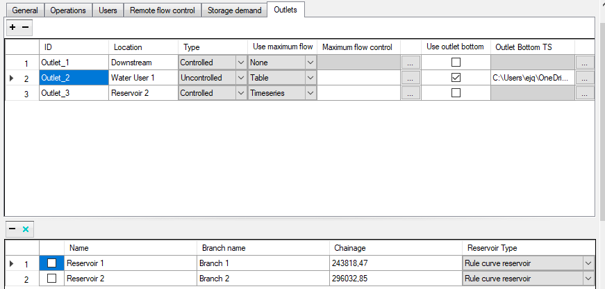
Figure 9.9 Outlet tab in user interface
Figure 9.9 illustrates an example where three outlets have been specified: 1) to the downstream channel, 2) to water user 1, and 3) to the reservoir N6. Notice, that no outlet has been specified for the hydropower plant node, since the hydropower plants has its own specifications to control the outflow through its outlet for power generation.
Example: Specifications of outlet_1 in the outlets table:
1. ID: Outlet_1; is the name of the outlet and used as item name in the results file.
2. Location states the name of the connected node or 'Downstream' for a connection down the river.
3. Type: Two types of outlets are available:
a. Controlled, as an outlet for which the outflow can be decided by the reservoir operation by closing the outlet partwise or completely.
b. Uncontrolled, where the outflow is determined by the hydrodynamic conditions of the reservoir and the outlet (reservoir water level and outlet bottom level). In other words, the outflow of an uncontrolled outlet cannot be determined by the reservoir operations.
4. Use Maximum Flow: This parameter specifies a possible capacity limitation of the outlet. The maximum flow can be specified in three ways:
a. None: there is no maximum outflow limitation. It is the default value.
b. Table: the maximum flow is determined by the hydrodynamic conditions of the reservoir and the outlet bottom level, described by a Q-H table. Q as the maximum outflow is derived by the water depth relative to the outlet bottom level (see point 5.), H.
c. Timeseries: the maximum flow of the outlet is determined by a discharge time series.
5. Use outlet bottom: if the checkbox is ticked, the user must provide a time series for the bottom level of the outlet. If unchecked, the considered outlet bottom level is the top of dead storage or, if one exists, the minimum operational level of the reservoir, depending on the type of connected node.
6. Outlet Bottom TS: if the "Use of outlet bottom" check box is ticked, the user must create, or select a time series for the outlet bottom levels. The specified item in the time series must be of water level type.
Note: If an outlet is of uncontrolled type, only a table can be used to determine the maximum outflow. As it is uncontrolled, that value is used for the simulation as routed water through the outlet. In a controlled outlet, the Q value from the table gives the outlet's maximum possible outflow. The actual outflow can be much lower or even zero.
Additional outlets connected to the downstream channel can be added by clicking the '+'-button. In this case, the reservoir operations will release water starting from the outlets with no specified bottom outlet followed by the ones from lowest to highest outlet bottom level. Furthermore, outlets can, if more than one is present, be deleted by selecting them and clicking the '-'-button.
The reservoir will only release water up to the capacity of the outlets (plus release to hydro power plants). An exception is, when the water level of the reservoir raises above the crest level of the reservoir. In this case it is understood that the spill doesn't go through any of the existing outlets, but over the crest level as an uncontrolled spill. In this case, it is possible to model a spill over the crest level as a controlled and unlimited outlet with a bottom level equal to the crest level.
Default controlled rules for controlled outlets
A number of default assumptions apply:
1. When no bottom level is specified for an outlet, the model assumes that the downstream channel has a bottom outlet at the dead storage level;
2. When no bottom level is specified, and the outlet is connected to a water user, the bottom level is assumed to be at the minimum operational level of the reservoir. If no minimum operational level is present, the dead storage level is used;
3. For a controlled outlet connected to a water user, the outlet will release water until the water user demand is completely satisfied, or the reservoir runs empty;
4. For a controlled outlet connected to another reservoir, the outlet will be controlled by the storage demand requirements. When these are satisfied, the outlet gate will be closed to stop any further release;
5. When an outlet is created by pressing the '+'-button in the outlets table, it will by default be created as controlled outlet with no limitation in its outflow capacity. Furthermore, no outlet bottom level will be specified. By doing so, it is ensured that all MIKE HYDRO Basin models created with MIKE versions before Release 2019 update 1 can run with current and future versions of the software and obtain equivalent numerical results;
6. There is no specification of outlets for hydro power plants, since these have a complete specification of the outflows for power generation and its hydrodynamics limitations with respect to the reservoir water levels;
7. It is assumed that the non-specified outlets to hydropower plants are by default-controlled outlets, controlled by the hydropower plant parameters, defined in the hydropower plant table.
It is relevant to mention that the downstream releases from the reservoir are affected by the existence of connected hydropower plants, particularly if these have excess capacity. In this case the hydropower plant will use the downstream release and return it back to the river.
Order of use when several outlets in the downstream direction
If a reservoir has two or more outlets discharging directly to the downstream river channel(i.e., not discharging through a hydropower plant or a water user with return flow), release will start from the outlets with lowest bottom level. When the capacity of this outlet has reached its maximum capacity, the next lowest outlet will be used, etc. Finally, when the the outlet with highest bottom level has reached its maximum outlet capacity, the reservoir will stop releasing water for the given time step. If two outlets have the same bottom level, the order is irrelevant for the simulation and the model will just release in the order given by the table.
Backward Compatibility of the legacy Spillways tab.
In models created before Release 2019 update 1, there was an optional specification of spillways, which is a simplified specification of an outlet management system. In a model created in a MIKE HYDRO Basin 2019 (not update 1!) or previous, the spillway tab looked like the following:
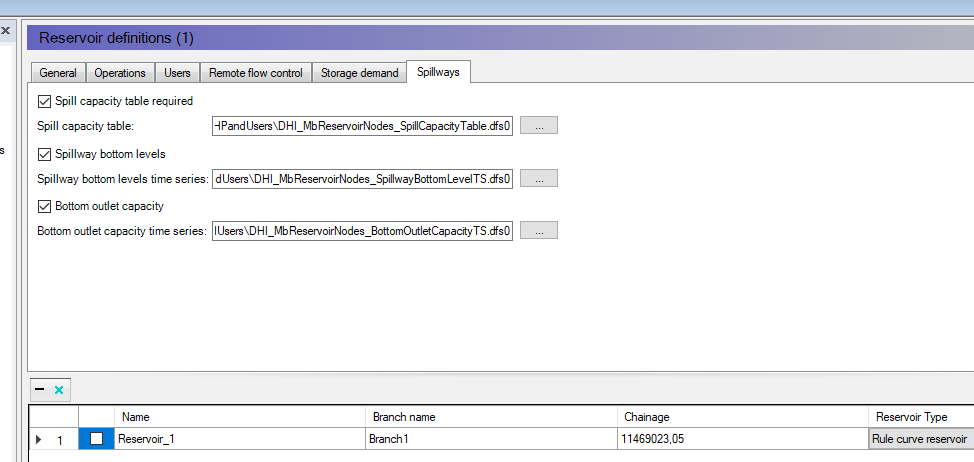
Figure 9.10 Values in old Spillway tab in User Interface
In the table a spillway capacity table, a spillway bottom outlet level time series, and a bottom outlet capacity time series have been specified. Opening the example above with a version including the outlets module, it is automatically translated to the following:
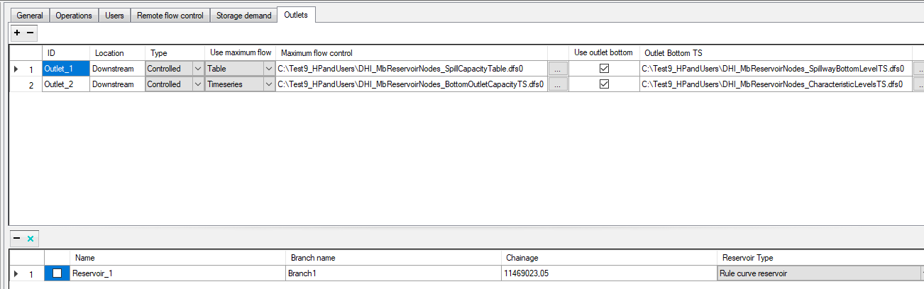
Figure 9.11 Values in new Outlets tab in User Interface
Two outlets to the river are created, 'Outlet_1', which is a controlled outlet with a maximum outflow specified by the 'Spill capacity table' and its outlet bottom given by the 'Spillway bottom levels' time series.
The second outlet, 'Outlet_2' is a controlled outlet as well. It is specified by the time series 'Bottom outlet capacity' as the maximum outflow. Besides, the outlet bottom TS is given explicitly as the top of dead storage, using the reservoir characteristics time series.
Note that, when creating a new reservoir, the default parameters for outlets are enough to run any model. Thus, the existence of the outlet parameters does not necessarily make the basin modelling more complicated than what is has been in the previous version of the software.
Outlet Simulation results
The simulation will from now on include extra items, specifying the outflow at each outlet. These appear as sub-items for each reservoir node in the results tree as seen in Figure 9.12.
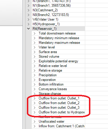
Figure 9.12 Sub-items for reservoir nodes in output
As one can see, there is an additional item for the outflow to the hydropower plant, even though there is no explicit specification of its outlet.
The item called "Downstream Spill" has been removed from Release 2019 update 1 on.
![]()