Internal Boundary Conditions
If a simulation with MIKE SHE AD includes more than one part of the hydrological cycle, the solute fluxes between the different hydrologic components must be kept track of. In principle, the solute fluxes between the components follow the water flow between the components. Multiplying the flow rate with the solute concentration produces a source/sink term for the relevant components. Table 33.1 lists the solute exchange possibilities between the components, in particular when one or more component is not included in the flow simulation.
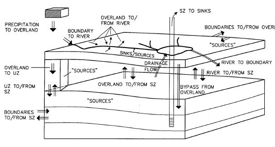
An sketch of the different internal boundary conditions is shown in Figure 33.1. Each of these exchanges is detailed in the respective sub-section for each hydrologic component.
Figure 33.1 Outline of the different transport possibilities between components and boundaries.
![]()