The amount of runoff generated by MIKE SHE depends on the density of the stream network defined in MIKE Hydro River. If the stream network is dense, then you will get more runoff in the model because the lateral travel time to the streams will be short, and the infiltration and evaporation losses will be smaller.
The Ponded Drainage function has been designed to facilitate a flexible definition of storm water drainage in both natural and urbanized catchments. In particular, the Ponded Drainage function supports the following features:
· In urban areas, paving and surface sealing (eg roof tops) limits infiltration and enhances runoff.
· Ponded water is routed to user-defined locations (boundaries, depressions, manholes and streams).
· The time varying storage in the drainage system is accounted for by different inflow and outflow rates.
· Drainage rates can be controlled by drain levels, drainage time constants and maximum outflow rates.
· Drainage is restricted if the destination water level is higher than the source water level.
· Urban development over time can be simulated by time varying drainage parameters.
· Overland flow is calculated normally for ponded water that does not drain in the current time step.
Conceptually, the Ponded Drainage function is shown in Figure 24.6.
Figure 24.6 Conceptualization of the Ponded Drainage function
Calculation order
The Ponded Drainage is calculate explicitly in a particular order with respect to the other hydrologic processes.
1. Rainfall is added to the ponded depth in the cell.
2. Then, OL Drainage will be immediately calculated.
In this way, the OL Drainage essentially acts on rainfall and removes rainfall before anything else happens.
If there is any ponded water remaining on the cell after the drainage has been removed, then it will be removed in the following order until no ponded water remains.
1. Evaporation is removed from the ponded water;
2. Then, Infiltration to the unsaturated zone will be calculated; and
3. Finally, Lateral Overland Flow will be calculated to the adjacent cells.
The Ponded Drainage is calculated for every cell independently. That is, the drainage that is calculated is not added to the destination cells until the end of the calculation for all the cells. This prevents circular drainage, and means that the order in which the calculation occurs is not relevant. After the ponded drainage is calculated, the depths in all the cells are updated - both sources and destinations. The calculation of ET, infiltration and lateral OL flow is based on the updated ponded depths.
Calculation method
Mathematically, the Ponded Drainage is calculated similarly to the Saturated Zone Drainage with the SOL solver.
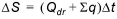
The new ponded water level at the end of the time step is calculated explicitly from the flow balance equation
where DS is the storage change per unit area as a result of a drop in ponding, Qdr is the specific outflow into the drain per unit area and Sq represents all other flow terms in a computational node.
Since, the ponded drainage is calculated independently in every cell, and before ET, infiltration and lateral overland flow, the Sq is zero in this formulation.
The change in storage per unit area can also be calculated from
where d0 is the depth of water above the drain at the beginning of the time step and dt is the depth of water above the drain after drainage occurs.
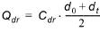
Qdr is calculated based on the mean depth of ponded water during the time step. Thus,
where Cdr is the drain leakage coefficient, or time constant, in units of [1/time].
Substituting (24.23) and (24.24) into (24.22) and rearranging, the water depth after drainage is calculated, dt, can be determined by
(24.25) 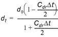
From which the new ponded water level elevation, ht, after drainage is calculated can be determined by
(24.26) 
where Zdr is the elevation of the drain.
Constraints
Several constraints have been added to the formulation to make the Ponded Drainage function more practical.
· Paved Fraction - a paved fraction for the cell is used to reduce infiltration in urban areas.
· Runoff Fraction - a runoff fraction for the cell is used to partition the ponded water into a fraction that can drain to the Ponded Drainage network, and a fraction that flows laterally with the Finite Difference Overland Flow.
· Detention storage - the Ponded Drainage will only affect the depth of ponding above the Detention storage. However, this can be changed by means of an Extra Parameter.
· Drain Level - the Ponded Drainage will occur only when the ponded depth exceeds the Drain Level
· Maximum drainage rate - a maximum drainage rate ensures that culvert capacities are not exceeded
· Downstream depth criteria - there is an optional check to ensure that the downstream drainage destination does not have a higher water level.
· Inflow time constant - the rate of inflow to the drains is controlled by a time constant.
· Outflow time constant - the rate of outflow to the destination is controlled by a time constant. If the outflow rate is less than the inflow rate, then water will accumulate on a cell-by-cell basis in the “drain”. There is currently no limit on the amount of water than can accumulate in the drain.
Reference Drainage System
The Reference System for linking drainage source and destination is calculated by the Pre-Processor. By default the drainage reference system is calculated downhill until either a local depression is found, or a stream or local boundary is encountered.
Optionally, the drainage can be routed to specified MIKE Hydro River nodes, or MIKE Urban Manholes.
![]()