Each Interflow Reservoir is treated as A Single Linear Reservoir with Two Outlets (p. 615). Thus, from Eq. 30.30, if the water level in the linear reservoir is above the threshold water level
where qI is the specific interflow out of the reservoir in units of [L/T], h is the depth of water in the interflow reservoir, hthresh is the depth of water required before interflow occurs, and ki is the time constant for interflow. If the water level is below the threshold there is no interflow.
Similarly, if there is water in the linear reservoir, specific percolation outflow can be calculated from
where h is again the depth of water in the interflow reservoir, and kp is the time constant for percolation flow. If the water level is at the bottom of the reservoir there is no percolation.
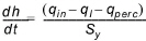
Combining Eqs 30.37 and 30.38 with the continuity equation
where, qin is the sum of inflow from an upstream Interflow reservoir and the infiltration from UZ, Sy is the specific yield, gives the following expression for h at time t when there is both qI and qperc (linear reservoir with two outlets)
(30.40) 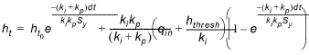
In the case where the water level is below the threshold, the formulation for a linear reservoir with one outlet applies, which yields
(30.41) 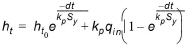
Inflow to the Interflow reservoir, qin, will normally be positive (i.e. water will be being added), but if evapotranspiration from the saturated zone is included or the net precipitation is used as input there might be a net discharge of water from the interflow reservoir. As the infiltration is a constant rate calculated explicitly in other parts of MIKE SHE, this will result in a water balance error if the interflow reservoir is empty. This will be reported in the log file at the end of the simulation.
From the level changes in the reservoir, the total average outflow can be calculated for the time step, dt. Thus, for the two outlet case,
(30.42) 
(30.43) 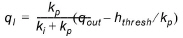
(30.44) 
and for the single outlet case (no interflow),
(30.45) 
If during a time step the reservoir level crosses one or more thresholds, an iterative procedure is used to subdivide the time step and the appropriate formulation is used for each sub-time step.
The discharge to the river, qI river, in the lowest Interflow Reservoir is simply the qI from that reservoir.
![]()