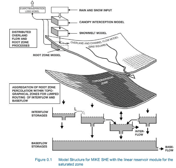
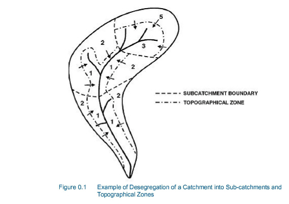
In the linear reservoir method, the entire catchment is subdivided into a number of subcatchments and within each subcatchment the saturated zone is represented by a series of interdependent, shallow interflow reservoirs, plus a number of separate, deep groundwater reservoirs that contribute to stream baseflow. An example of a subdivision of a catchment area is outlined in Figure 30.8, where the topographical zones represent the interflow reservoirs in the model. If a river is present, water will be routed through the linear reservoirs as interflow and baseflow and subsequently added as lateral flow to the river. If no river is specified, the interflow and baseflow will be simply summed up and given as total outflow from the catchment area. The lateral flows to the river (i.e. interflow and baseflow) are by default routed to the river links that neighbour the model cells in the lowest topographical zone in each subcatchment.
Interflow will be added as lateral flow to river links located in the lowest interflow storage in each catchment. Similarly, baseflow is added to river links located within the baseflow storage area.
The infiltrating water from the unsaturated zone may either contribute to the baseflow or move laterally as interflow towards the stream. Hence, the interflow reservoirs have two outlets, one outlet contributes to the next interflow reservoir or the river and the other contributes to the baseflow reservoirs. The baseflow reservoirs, which only have one outlet, are not interconnected.
Normally, one reservoir should be sufficient for modelling baseflow satisfactorily. However, in some cases, for example in a large catchment, hydraulic contact with a river is unlikely to be present everywhere. In this case, more than one reservoir can be specified.
In low areas adjacent to the river branches the water table may, in periods, be located above or immediately below the surface. In this case, it will contribute more to total catchment evaporation than the rest of the area. To strengthen this mechanism water held in the part of the baseflow reservoirs beneath the lowest interflow zone may be allowed to contribute to the root zone when the soil moisture is below field capacity.
Previous experience with lumped conceptual models shows that the linear reservoir approach is sufficient for an accurate simulation of the interflow and baseflow components, if the input to the reservoirs can be assessed correctly and the time constants of the outlets are known. Due to the distributed approach and physically based representation used in MIKE SHE in the overland and unsaturated zone flow components, an accurate simulation of soil moisture drainage in space and time is provided in MIKE SHE for the linear reservoir module. The time constants on the other hand are basically unknown for an ungauged catchment but a fair estimate may be obtained from an evaluation of the hydrogeologic conditions and/or from gauged catchment with similar subsurface conditions.
If the UZ feedback is not included, uncertainty of the time constants will only affect routing of the baseflow and interflow components while the total volumes of runoff will remain unchanged.
If UZ feedback from the baseflow reservoir is included, some of the baseflow to the stream will be transferred to the UZ storage because of ET in the unsaturated zone.
![]()