The potential flow is calculated using Darcy's law
where Dh is the piezometric head difference and C is the conductance.
The horizontal conductance in Eq. (30.2) is derived from the harmonic mean of the horizontal conductivity and the geometric mean of the layer thickness. Thus, the horizontal conductance between node i and node i-1 will be
(30.3) 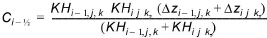
where, KH is the horizontal hydraulic conductivity of the cell and Dz is the saturated layer thickness of the cell.
The vertical conductance between two cells is computed as a weighted serial connection of the hydraulic conductivity, calculated from the middle of layer k to the middle of the layer k+1. Thus,
(30.4) 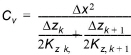
where Dz is the layer thickness
Dewatering conditions
Consider the situation in Figure 30.1, where the cell below becomes dewatered.
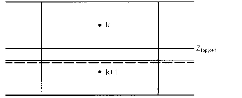
Figure 30.1 Dewatering conditions in a lower cell.
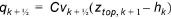
The actual flow between cell k and k+1 is
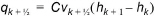
In the present solution scheme the flow will be computed as
Subtracting Eqs.(30.5) from (30.6) gives the correction term
(30.7) 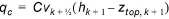
which is added to the right-hand side of the finite difference equation using the last computed head.
A correction must also be applied to the finite difference equation if the cell above becomes dewatered.
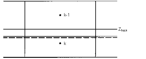
Figure 30.2 Dewatering conditions in the cell above
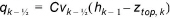
Thus, from Figure 30.2, the flow from cell k-1 to k is
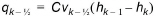
where, again the computed flow is
Subtracting Eqs. (30.8) from (30.9) gives the correction term
(30.10) 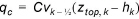
which is added to the right-hand side of the finite difference equation using the last computed head
![]()