Subcatchments and Linear Reservoirs
Three Integer Grid Code maps are required for setting up the framework for the reservoirs,
· a map with the division of the model area into Subcatchments,
· a map of Interflow Reservoirs, and
· a map of Baseflow Reservoirs.
The Interflow Reservoirs are equivalent to what was called the Topographic Zones in earlier versions of the Linear Reservoir module in MIKE SHE. There is no limit on the number of subcatchments, or linear reservoirs that can be specified in the model.
The division of the model area into subcatchments can be made arbitrarily. However, the Interflow Reservoirs must be numbered in a more restricted manner. Within each subcatchment, all water flows from the reservoir with the highest grid code number to the reservoir with the next lower grid code number, until the reservoir with the lowest grid code number within the subcatchment is reached. The reservoir with the lowest grid code number will then drain to the river links located in the reservoir. If no river links are found in the reservoir, then the water will not drain to the river and a warning will be written to the run log file. For example, in Figure 30.9 Interflow Reservoir 2 always flows into Reservoir 1 and Reservoir 1 discharges to the stream network. Likewise, Reservoir 5 flows into 3, which discharges to the stream network.
For baseflow, the model area is subdivided into one or more Baseflow Reservoirs, which are not interconnected. However, each Baseflow Reservoir is further subdivided into two parallel reservoirs. The parallel reservoirs can be used to differentiate between fast and slow components of baseflow discharge and storage.
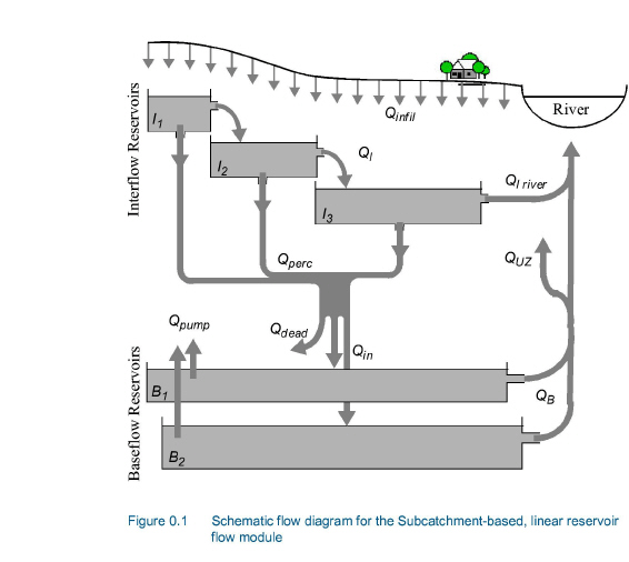
Figure 30.10 is a schematization of the flow to, from and within the system of linear reservoirs. Vertical infiltration from the unsaturated zone is distributed to the Interflow Reservoirs (Qinfil). Water flows between the Interflow Reservoirs sequentially (QI) and eventually discharges directly to the river network (QI river), or percolates vertically to the deeper Baseflow Reservoirs (Qperc). The parallel Baseflow Reservoirs each receive a fraction of the percolation water (Qin) and each discharges directly to the river network (QB). Groundwater can be removed from the Baseflow Reservoirs via groundwater pumping (Qpump). If UZ feedback is included, then some of the baseflow to the stream will be added to the UZ storage (QUZ) and subsequently removed from the unsaturated zone via ET.
In some situations, the interflow reservoirs will not correspond to the areas of active baseflow in the current catchment. That is, some percolation from the interflow reservoirs may contribute to baseflow in a neighbouring watershed. This has been resolved by introducing a dead zone storage (Qdead) between the Interflow and Baseflow Reservoirs
![]()