Definition of vertical UZ numerical grid
The Gravity and Richards Equation methods assume that the soil profile is divided into discrete computational nodes. The non-linearity of the unsaturated flow process creates large gradients in soil pressure and soil moisture content during infiltration. Therefore, it is important to select appropriate nodal increments, so as to describe the flow process with sufficient accuracy but at the same time keeping the computational time reasonable. This trade off can become a key constraint in catchment-scale simulations.
Note: The UZ model only connects to the top layer of the SZ model. All nodes below the water table are ignored. All nodes below the bottom of SZ layer 1 are also ignored. However, results will be output at all of these nodes, which can lead to unnecessarily large output files. There is also a small memory overhead associated with the extra nodes, but the extra nodes cause very little computational overhead
The simulation of Hortonian ponding at the ground surface (high rainfall intensity on dry, low permeable soil) requires a fine spatial resolution in the upper part of the profile (see Figure 29.3). Deeper in the profile the gradients are smaller and larger node increments can usually be selected. However, in the case of coarser grained soils, there may again be very high saturation gradients near the water table. Thus, as a general guideline, one should choose a finer spatial resolution in the top nodes.
The discretisation should be tailored to the profile description and the required accuracy of the simulation.
· If the full Richards equation is used the vertical discretisation may vary from 1-5 cm in the uppermost grid points to 10-50 cm in the bottom of the profile.
· For the Gravity Flow module, a coarser discretisation may be used. For example, 10-25 cm in the upper part of the soil profile and up to 50-100 cm in the lower part of the profile.
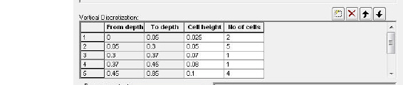
The vertical discretization is defined in the lower half of the soil profile dialogue.
From and To Depths refers to the distances to the top and bottom of the soil layer, below the ground surface. Neither are directly editable since they are calculated from the number of cells and their thicknesses.
Cell Height is the thickness of the numerical cells in the soil profile.
No. of Cells is the number of cells with the specified cell height. Together these two values define the total thickness of the current section.
Note: the soil properties are averaged if the cell boundaries and the soil boundaries do not align.
Note: The boundary between two blocks with different cell heights, the two adjacent boundary cells are automatically adjusted to give a smoother change in cell heights.
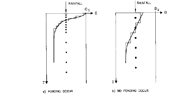
Figure 29.3 Examples of different increments in the soil profile and the resulting water content distribution of 1-3 cm for detailed studies and 3-5 cm for catchment studies. Further down in the profile larger increments can be chosen ranging from 10 cm to 30 cm.
![]()