You can choose between the following nine different types of boundary conditions
· Wave parameters (Version 1 and 2)
· Wind-sea and swell parameters (Version 1 and 2)
Specifying a closed boundary corresponds to having land along the boundary, i.e. no waves enter the model domain through this boundary and the outgoing waves are fully absorbed. This type of boundary is utilized if no wave data is available.
Wave parameters (Version 1 and 2)
Selecting one of the two wave parameters options a parametric representation of the spectral distribution is used. You must specify the following wave parameters at the boundary
· Significant wave height, Hm0
· Spectral peak period, Tp
· Mean wave direction, MWD
· Directional spreading index, n (Version 1) or
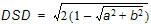
· Directional standard deviation, DSD (Version 2)
In Version 1 the directional spreading index n is specified, while in Version 2 the directional standard deviation is specified.
For the fully spectral formulation the distribution in the frequency domain is a JONSWAP spectrum with standard shape parameters (g=3.3, sa=0.07 and sb=0.09).
Using the directional decoupled parametric formulation the calculations is based on the action-averaged angular wave frequency, w0. Hence, using this formulation a relation between the action-averaged angular wave frequency and the peak period is needed. In the model the following relationships are used. For the JONSWAP spectrum with standard shape parameters the relationship between the action-averaged angular wave frequency, W0, and the energy-averaged angular wave frequency, w0, is given by w0/W0=0.92 and the relationship between the peak period, Tp, and the energy-averaged angular wave frequency, W0, is given by W0=2p/Tp/0.83.
For the directional distribution a cosn(q-qm) distribution is used, where n is the directional spreading index and qm is the mean wave direction (MWD). The mean wave direction is defined with respect to true North (coming from). When the directional standard deviation, DSD, is specified (Version 2) an equivalent directional spreading index is determined.
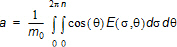
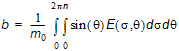
The directional standard deviation DSD is defined by
where
The relationship between the directional spreading index and the directional standard deviation is presented in Table 6.1 below.
The energy spectrum at the boundary is scaled so that the energy in the discrete part of the spectrum corresponds to the specified energy at the boundary.
Wind-sea and swell parameters (Version 1 and 2)
Selecting one of the two wind-sea and swell parameters options the energy spectrum at the boundary is determined as the superposition of the energy spectra determined from the wave parameters for wind-sea and the wave parameters swell. Both spectra are determined as described in the precious section "Wave parameters (Version 1 and 2)". For the wind-sea part of the spectrum the standard shape parameters for a JONSWAP spectrum are used and for the swell part the peakedness parameter is changed to g=5.0.
Note, that this type of boundary conditions can only be used for the fully spectral formulation.
Selecting the wave action spectrum option you must specify the following parameters
· using the directionally decoupled parametric formulation two items must be specified: the zero-th moment m0(q), e.g. expressed by [m2/rad], of the normal wave action spectrum and the first-order moment m1(q), e.g. expressed by [m2s/rad], of the normal wave action spectrum. Here q is the wave direction.
· using the fully spectral formulation, the input spectrum is the normal wave action spectrum N(s,q ), e.g. expressed by [m2s2/rad]. Here s is the relative angular frequency and q is the wave direction.
Selecting the wave energy spectrum you must specify normal energy spectrum E(f ,q ), e.g. expressed by [m2s/rad]. Here f is the relative frequency and q is the wave direction.
For this type of boundary condition a one-dimensional calculation of the basic equations is solved along the boundary line. The information of the incoming waves in the start point and the end point of the line are obtained from the connected boundary lines.
This type of boundary conditions is a good approximation when the boundary line is almost straight and when the depth contours is almost perpendicular to the line.
When specifying a reflective boundary no waves can enter the model domain through this boundary, and the outgoing waves are reflected from the boundary. The amount of wave reflection is controlled by the specified reflection coefficient, R. When the value is 0 the outgoing waves are fully absorbed, and when the value is 1 outgoing waves are fully reflected. In between the waves are partial reflected.
The specified reflection coefficient, R, describes the intensity of a reflected wave height relative to an incident wave height. The corresponding reflection of the wave energy for each individual spectral bin is taken as R2. Hence it does therefore not permit coherent wave fields in the computational domain (eg. harbours with standing-wave patterns are excluded).
![]()