The MIKE 21 hydrodynamic model requires you to specify either the surface elevation or flux at all open boundary points specified on Boundary.
The choice of variation at an open boundary can be either level or flux (the flux is the total amount of discharge passing the open boundary). Actual values, level or flux, at each boundary can be specified in one of five different formats:
In the first case, you specify the constant value (constant both in space and time) to be applied along the whole boundary.
For sinusoidal variation, you must specify the reference level, range, period and phase of the sine series.
When selecting time series boundary variation, you must specify the name of a type 0 data file. The temporal variation given in this file is applied along the whole boundary.
For line series, the temporal variation along the boundary is obtained from the specified type 1 data file.
In the case of transfer data, boundary values are obtained from the results of another simulation, i.e. from a transfer data file generated by the “Transfer boundary tool”, M21trn, in the MIKE 21 Toolbox.
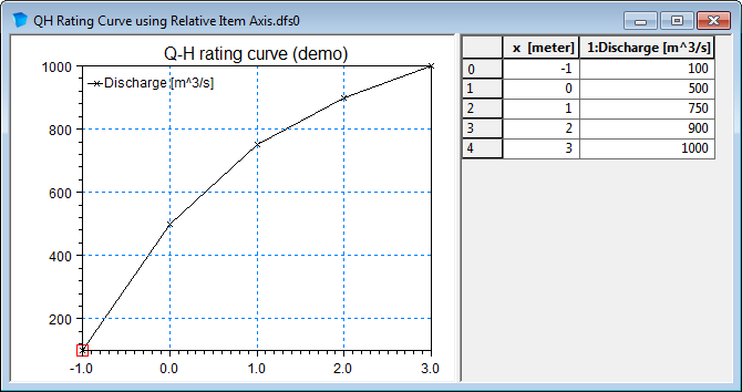
In the case of Rating curve you must specify a dfs0 time series representing the relation between discharge and water level (specified by the relative axis). The discharge values in the rating curve should be supplied as non-negative values. MIKE 21 Flow Model will during the processing make sure that the discharge in the QH relation will be effectuated as an outflow at the boundary. The use of Rating curve is only recommended for downstream boundaries where water flows out of the model.
Figure 5.1 Example of Rating curve
FAB type
The FAB type selects the strategy for calculating the fluxes along the open boundary. See the manual for a description and discussion of available options.
Tilting
Tilting of a boundary is a facility that generates a setup along the open boundary so that the slope of the surface elevation is in equilibrium with the wind stress and Coriolis force. It should only be applied if the flux along the boundary is negligible. You may select “linear tilting” or “non-linear tilting” and set the tilt point. In the linear approach the bed slope is assumed to be constant whereas in the non-linear approach the actual water depth is taken into consideration. The linear approach results in a more stable solution, the non-linear is more precise, but over a jagged bed spurious fluctuations may occur. With respect to the tilting point, it is a good first guess to select the deepest point along the boundary. However, trial and error in some cases is a way to obtain the best results.
Flow direction
Default flow directions are perpendicular to the open boundary. In those situations where this can not be assumed, the possibility exists for specifying the directions. See Boundary Conditions (p. 87).
![]()