A culvert may be of three different geometries:
· Rectangular
· Circular
· Irregular (A level-width table)
Geometry
With the rectangular and the circular type geometries the width/height or the diameter is supplied.
For the Irregular type geometry the geometry is to be defined through a level-width relationship table, see Figure 6.28. Further the user must supply the invert levels of the culvert on the upstream and on the downstream side. The invert is the lowest point in the inlet/outlet section. Note that the values in the level width table are taken with respect to the inverts. Further the user must supply the length of the culvert (in the flow direction) and the resistance in the culvert. The latter is defined through the use of Manning's n (=1/M).
Figure 6.28 Definition sketch of irregular level-width culvert geometry
A culvert structure can be modelled as an open section if required by setting the Closed / Open switch. An example where this may be used is a “long” weir where the friction along the length of the weir is of importance and/or the flow areas at the entrance and exit are significantly different.
If set to open the culvert will never run full or partially full, therefore only those flow conditions which represent a free water surface are modelled. When the water level is higher than the soffit the hydraulic parameters are calculated based on a section extended vertically upwards with a width equal to that at the soffit. For example, in the case of a rectangular section the height value is essentially redundant as the cross-section will be modelled as an open section of constant width.
In the case of a circular section, this switch is invalid and will be set to closed.
The total head loss, DH through a culvert is given by:
(6.28) 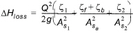
where As is the mean cross section area along the length of the culvert and Q is the discharge, z1 is the entrance or contraction loss, z2 is the outlet or expansion loss, zf is the Friction loss calculated using the Manning formula and zb is the bend loss coefficient.
(6.29) 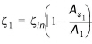
(6.30) 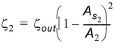
(6.31) 
where L is the culvert length, n is Manning's coefficient and R is the mean Hydraulic Radius along the culvert. The Manning's n-value depends on the interior surface of the culvert. Table values can be found in literature. For e.g. a concrete culvert n would typically range from 0.011 to 0.017.
The bend loss coefficient, zb, is provided for situations where head losses other than from the above occur, for example bends, damaged culverts, trapped debris. For straight culverts in good condition a value of zero would apply.
Free overflow head loss factor
The critical flows (and orifice flows for culverts as well) are multiplied by the critical flow correction factor, ac, specified as the Free Overflow Head Loss Factor. Typically a value of 1.0 is used.
![]()