Recommended selections and values
If you specify water levels for a boundary you can normally assume that there is no spatial variation along the boundary. However, in certain situations you may wish to specify a non-horizontal water level since a horizontal water level may give unrealistic results. These situations are treated in the following way:
· If, for example, you are carrying out a tidal study and have a tidal station at each end of the open boundary, a linear variation along the boundary (or parts of it) should be specified. You do that by having a type 1 data file with the boundary conditions. The data file can be created with Profile Editor under MIKE Zero.
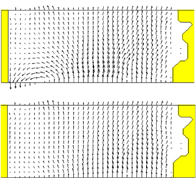
· Another situation where a horizontal water level at the boundary is unrealistic is in the presence of wind and the Coriolis force. If you keep the water level horizontal you will get a large inflow together with a large outflow at the same boundary, especially in a steady state situation, as the water level should actually be tilted. The effect is illustrated in Figure 6.13. You should therefore specify a tilt point so that MIKE 21 will tilt the boundary to avoid this unrealistic flow pattern.
Figure 6.13 Before (upper) and after (lower) the tilting
MIKE 21 provides two alternatives for the tilting approach:
· linear tilting
· non-linear tilting.
With a selection of linear tilting MIKE 21 assumes the water level to follow a straight line which can be rotated around the tilting point. This approach has the advantage of smoothing the effects originating from a very jaggered seabed.
The non-linear approach is more theoretically correct and provides a better estimate in many cases where you have a gentle slope on the seabed. The tilting is calculated in each point along the boundary based on the steady state Navier Stokes equations.
It is assumed that the flow is perpendicular to the boundary. However, the correction of the flow will also work if the flow direction is nearly perpendicular to the boundary. You should keep this in mind when selecting how the fluxes along the boundary should be calculated: the method called type 12 together with a perpendicular inflow is recommended.
The difficulty in using the tilt facility lies in the specification of the tilt point. A good choice to begin with is the deepest point along the boundary. However, you might have to find the best point through trial and error.
If you have two adjacent boundaries you should also be careful not to create a conflicting situation in the corner.
If you specify the total flow through your boundary and select that it should be distributed relative to the depth, it will be distributed as it would have been in a uniform flow field with the Manning resistance law applied, i.e. is relative to h5/3, where h is the depth. This distribution is, in most cases, the best one that can be applied.
![]()