Specifying the pier resistance
If the resistance effect on the flow from bridge piers has to be included in the simulation, the position and geometrical layout of the piers must be specified.
This various information must be grouped together in a pier data file. A pier data file is a type 1 data file where the number of time steps in fact is the number of piers, i.e. the time axis in the data file is not a true time axis. In the same way, the spatial axis is not a true spatial axis, but merely a collection of data describing the pier.
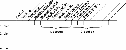
The pier data file has the layout depicted in Figure 6.18.

Figure 6.18 Layout of pier data file
The data file is created with the Profile Editor tool. In the following the parameters of the file are described:
· The x- and y-coordinates must be specified as map projection coordinates, e.g. UTM-33 coordinates.

Note: The map projection is defined by the Geographical Information in the data file (in Release 2007 and previous the projection system was defined by the item description, e.g. PROJ=UTM-33).
· The type 1 data file must have Data Type=800.
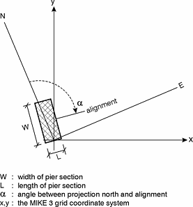
· The angle is measured from projection north to the alignment, positive clockwise and in degrees. Note that projection north is not the same as geographical north.
· The number of sections means the number of pier segments, i.e. the number of parts with different geometrical layout.
· The streamline factor is a factor that is multiplied on the total drag force to take into account the increased flow velocity due to the blocking of piers. A typical value is 1.02.
· The following five parameters describe the geometrical layout of one pier section. These five parameters have to be repeated at each section of the pier. The pier section type can be one of:
0: circular
1: rectangular
2: elliptical
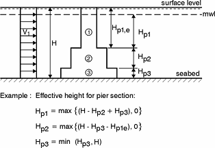
See Figure 6.19 and Figure 6.20 below for a definition sketch.
For a circular pier section please note: Both width and length should be equal to the diameter of the pier section and the parameter “Radius of rounded corners” is not used but should be assigned a value e.g. 0 or 1.

Figure 6.19 Pier definition sketch

Figure 6.20 Definition sketch. Effective height