In case the open boundaries do not correspond to those you had planned, you must specify “User specified” boundaries and then give the number of open boundaries in the model. Further you will in the boundary definition dialog have to specify the location of the open boundary. That is the coordinates of the first water point and the last water point along the boundary grid line.
It will be very unusual that you yourself have to specify the locations of the open boundaries. It is only relevant in the following two situations:
· You have a long open boundary broken by, say, two small islands. The menu will show you this boundary as three smaller boundaries. If the boundary conditions are either the same for all three boundaries or it is most conveniently to keep the boundary data for the whole boundary in the same type 1 data file, or transfer file, you can define the three boundaries as one boundary.
You will then have to specify the start point as the first water point on the first line and the last point as the last water point on the third line. The boundary line will then contain a few land points; but this is not an error.
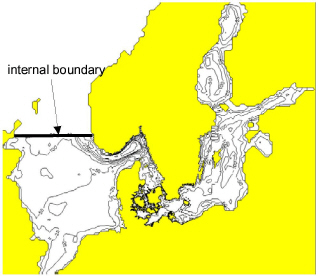
· You want to have an internal open boundary in your model. An internal boundary is a boundary that is not located on one of the model sides. You can use an internal boundary to keep your model size small, see Figure 6.11.
Note: If you want to include an internal boundary in your model, you must fill the area behind the boundary with land points.
Figure 6.11 Example of internal boundary
Due to the computational structure of MIKE 21 there are a few restrictions to where a boundary can be located, see Figure 6.12.

Note: All water points on the model sides must be included in an open boundary definition.
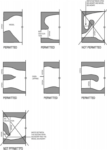
Figure 6.12 Restrictions on the location of an open boundary
![]()