There are three types of weirs available
The geometry of each of these is to be supplied by the user according to the sections below.
For a broad crested weir the user describes the shape of the “hole” through a level/width table (see figure below). The datum value for the structure may be used to shift the levels by a constant amount. The latter is typically used if the weir geometry has been surveyed with respect to a local benchmark.
Figure 6.26 Definition sketch of broad crested weir geometry
The standard formulations for flow over a broad crested weir are established automatically by the program on the basis of the weir geometry and the user specified head loss and calibration coefficients. These formulations assume a hydrostatic pressure distribution on the weir crests. Different algorithms are used for drowned flow and free overflow, with an automatic switching between the two.
For the weir formula 1 description the parameters are given by Figure 6.27. The width is perpendicular to the flow direction. Typically the invert level coincides with the overall datum.
Weir formula 1 is based on a standard weir expression, reduced according to the Villemonte formula:
(6.23) 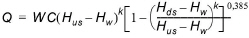
where Q is discharge through the structure, W is width, C is weir coefficient, k is the weir exponential coefficient, Hus is upstream water level, Hds is downstream water level and Hw is weir level (see Figure 6.27).
Figure 6.27 Definition sketch for weir flow
For the weir formula 2 the geometry is given by a crest level and a width. The crest level is taken with respect to the global datum. The width is perpendicular to the flow direction.
Weir formula 2 is the Honma formula:
(6.24) 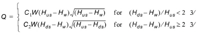
where Q is the discharge through structure, W is the width, C1 is the weir coefficient 1, and C2, the weir coefficient 2, is calculated according to  , Hus is the upstream water level, Hds is the downstream water level and Hw is weir level (see Figure 6.27).
The flow description generally used for a structure is given by:
(6.25) 
where DH is the energy loss over the structure, zt is the total head loss coefficient and Vs is the mean cross sectional velocity at the structure.
The total head loss coefficient (zt) is composed of entrance (z1) and exit (z2) coefficients. The coefficients are generally related to the input parameters for Inflow (zin) and Outflow (zout) and the changes in velocity (v) and area (A):
(6.26) 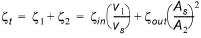
where suffix '1' and '2' represents velocity and Area on inflow and outflow side of structure respectively, and 's' represents the velocity and Area in the structure itself.
For subcritical flow through a structure there is an upstream contraction and a downstream expansion, so the above equation works fine.
However, in the present implementation, upstream and downstream cross sections are not extracted and accordingly, tabulated relations on cross section areas as function of water levels are not known. Instead, upstream and downstream areas are set to a large number resulting in a full loss contribution from the head loss factors defined. Viz,
(6.27) 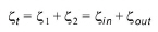
Care must be taken when selecting loss coefficients, particularly in situations where both subcritical and supercritical flow conditions occur. When flow conditions change from subcritical to supercritical (or the Froude number FR becomes greater than 1), the loss coefficients zin and zout (specified in the box) are modified:
· If FR > 1 in upstream h-point then zin = zin / 2
· If FR > 1 in downstream h-point then zout = zout / 2
Free Overflow Head Loss Factor
The critical flows (and orifice flows for culverts as well) are multiplied by the critical flow correction factor, ac, specified as the Free Overflow Head Loss Factor. Typically a value of 1.0 is used.
![]()