Include boundary
The boundary condition is applied in the simulation only if the option is checked.
Use mixing
This option should be active for boundaries where outflows from the model area take place, and where the boundary can become an inflow during the simulation (e.g. due to tidal conditions).
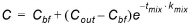
When the boundary becomes an inflow, the boundary condition is adjusted according to:
Where:
Cbf is the concentration specified at the boundary location
Cout is the computed concentration at the boundary immediately before the boundary became an inflow
Kmix is the mixing coefficient specified for the boundary
Tmix is the time since the boundary became an inflow.
When outflows occur at the boundary, the boundary condition is defined as:

Mixing coefficient
The mixing coefficient required when the option 'Use mixing' is active is specified here.
AD/WQ boundary overview table
The lower table is used to define the boundary values for each component to be described in the active boundary. Components are added or deleted from this table using the Append '+' or Delete '-' buttons above the table. For each component, the following data must be specified. Additionally, the 'Copy to selected boundaries' button may be used to add the content of the table from the active boundary to the selected boundaries.
Component
The component is selected from this list. Any component from the 'Components' menu may be selected.
Unit
Unit in which the boundary value is expressed. This field cannot be changed and is inherited from the 'Components' menu.
Boundary type
The boundary may be defined using one of the two types below:
· Concentration: Boundary input is specified as a concentration (mass/volume) and the simulation engine will multiply the HD inflow at the boundary location to define the total mass entering the river at the boundary location
· Load: Boundary input is specified as a specific load (mass) which is directly applied in the simulation engine as the load at the specific location. An eventual HD inflow source at the boundary location is hence not used to determine the mass inflow to the model.
Input type
Here the boundary can be defined as a constant value during the simulation or a time varying value.
Scale
The boundary condition value (constant or time series) will be multiplied by the specified Scale factor. This factor may be used to edit the boundary conditions without changing the input values.
Constant
The boundary value must be specified here when the Input type is set to 'Constant'.
AD file name
When the Input type is set to 'Time varying', the time series containing the boundary values must be selected here.
AD file item
This field shows the selected item in the time series, when the Input type is set to 'Time varying'.
Create AD/WQ Boundaries
Pressing this button will automatically create a boundary for all AD/WQ components on all existing boundaries.
For each AD/WQ boundary, the attribute 'Include boundary' is automatically set to true. The table is also filled with all components, with default parameters. Further adjustments of parameters may then be applied manually.
If AD/WQ boundaries already exist before pressing the button, a pop-up window asks whether existing AD/WQ boundaries should be overwritten or not. Pressing 'Yes' resets existing boundaries to default values, whereas pressing 'No' only inserts boundaries at locations where they don't already exist.
View all AD/WQ Boundaries
This button opens a new window which gives an overview of all existing AD/WQ boundaries, without having to navigate between each HD boundaries.
Data may be edited from this table, and sorted by clicking in the headers of the table.
![]()