Bed resistance values
Approach
Two approaches may be applied for the bed resistance. Either a uniform or a so-called multiple zones approach.
With the Uniform section approach, the bed resistance is defined by a resistance formula and associated global/local values, if the 'Resistance type' has been set to 'Relative resistance' for the cross section. The resulting bed resistance number applied in the simulation is the defined bed resistance multiplied by the water level dependent `Resistance factor' which is specified for the cross sections in the cross section editor (saved in .xns11 files).
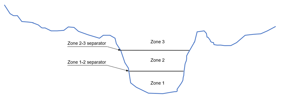
With the Multiple zones approach, the same rules apply, but it also offers a possibility for the user to divide the cross sections in a number of zones with different bed resistance values. These zones would typically represent the various areas with a local bed resistance value (e.g. a zone without vegetation at the bottom of the cross section, a vegetation zone on banks, etc.) as illustrated in Figure 8.1.
Figure 8.1 Multiple zones descriptoin of a cross-section
The resulting bed resistance numbers applied in the simulation are the zone values multiplied by the `Resistance factors' specified for the cross sections in the cross section editor.
Zones separators, defining the threshold level or depth between two consecutive zones, must be specified in the 'Zones separators' tab.
During the simulation, the bed resistance applied to the cross section will vary in time as a function of the water level: at each time step, the bed resistance from the zone in which the water surface is, will apply uniformly to the whole cross section.

Note: Bed resistance values are actually applied to processed data of the cross section. Each row from the processed data table gets the bed resistance value from the zone corresponding to the row's level. Interpolation will apply afterwards during the simulation, between the processed data levels.
Resistance formula
Four resistance type options are available from the drop-down menu:
· Manning's M (unit: m1/3/s, typical range: 10-100)
· Manning's n (reciprocal of Manning's M, typical range: 0.010-0.100)
· Chezy (C)
· Darcy-Weisbach (k)
For more information on the resistance formulas, please refer to MIKE 1D Reference Manual.
Resistance numbers specified in this dialogue window are a combination of a ‘Global value’ and possibly one or more ‘Local values’.
Global value
For the Uniform approach, a global resistance value must be specified, which is applied throughout all calculation points in the network, unless local values have been defined.
For the Multiple zones approach, a global number of zones must be specified, which is applied to all calculation points of the network unless local bed resistance values with a different number of zones is specified. The bed resistance values for each of the global zones must also be specified.
Local values
Local values are applied at specific locations defined by Branch name and Chainage.
To add a local value it can either by done through the tabular view or by digitising a resistance location through the Map view:
· In Map view, open the Spatial data ribbon
· select ‘Bed resistance’ from the ‘Type’ drop-down menu.
· click the ‘Add’ button and click on the desired location of the local bed resistance value.
· Location will automatically be added to the list in the Local values table and a resistance value may be entered.
If two or more local values are defined, the intermediate values will be calculate by linear interpolation.
For the Multiple zones approach, a local number of zones must be specified. This local number of zones can only apply if corresponding local zones separators also exist on the same reaches of rivers. Therefore, if a local bed resistance location is added, but if no local zone separators exist, the local bed resistance is defined with the global number of zones.

Example: A global resistance value of ‘Manning's M’ 30 is specified. Exceptions from the global value has been specified with Local values in other branches where resistance numbers will vary according to the defined table values between the specified chainages.
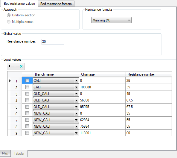
Figure 8.2 Bed resistance example
Zone separators
Global values
The global zones separators must be specified, when the Multiple zones approach is used. Global zones separators are applied throughout all calculation points in the network, unless local zones separators have been defined.
Zones separators' values may either be expressed as depths or levels. When expressed as depth, the specified depths represent the height from the bottom of the cross section up to the zone separators. Depths for the consecutive zone values must therefore increase.
Local values
Local zones separators must be specified at locations where a local number of zones is expected.
Zones separators' values may either be expressed as depths or levels. When expressed as depth, the specified depths represent the height from the bottom of the cross section up to the zone separators. Depths for the consecutive zone values must therefore increase.

Note: Local bed resistance values must be specified on all river reaches where local zones separators are specified.
Bed resistance factors
By activating the 'Include resistance factors' option, it is possible to apply factors/coefficients to the bed resistance values, which can either be constant in time or time varying. This facility e.g. allows to apply seasonal variations of bed resistance.
Applying a resistance factor higher than 1 will decrease the actual roughness of the river bed, whereas a value lower than 1 will increase the actual roughness. So when the resistance type is Manning (M), then the Manning's M value is multiplied by the factor. When the resistance type is Manning (n), then the Manning's n value is divided by the factor. This applies regardless if the cross sections use a relative or Manning resistance value: if a cross section uses a Manning resistance value, then the resistance factor is applied to its processed data.
Resistance factors specified in this dialogue are a combination of a 'Global value' and possibly one or more 'Local values'.
Global value
A global resistance factor value or time series, which is applied throughout all calculation points in the network, unless local values have been defined.
Local values
Local values are applied at specific locations defined by Branch name, Upstream chainage and Downstream chainage. For each local value, it is also possible to apply either a constant value or a time series.
![]()