Assign resistance from map layer
The tool 'Assign resistance from map layer ' may be used to update the distributed resistance values within cross sections using a raster or shape file layer.
Layer type
Two layer types are supported to specify the resistance values:
· Raster: The bed resistance layer must be a raster, mapping the bed resistance values. With this option, the cross sections are assigned the bed resistance values from the underlying raster cells.
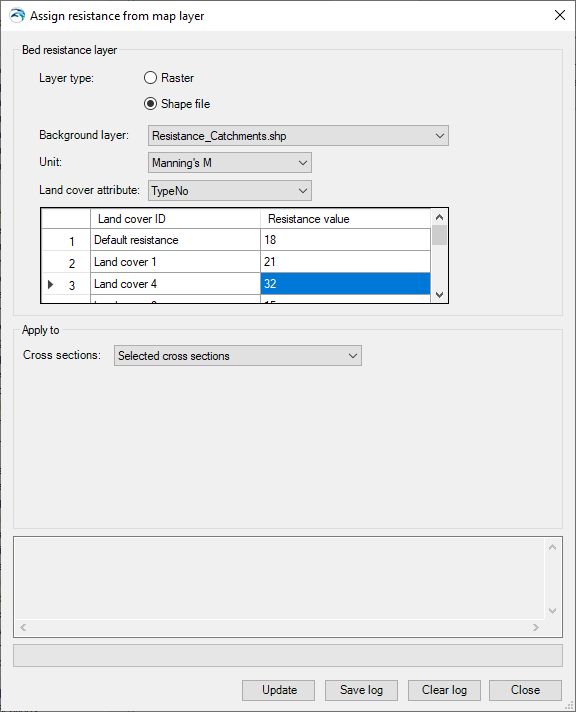
· Shape file: The bed resistance layer must be a polygon shape file, mapping the land cover. The shape file must contain an attribute specifying the land cover type for each polygon. This attribute must be an integer number. The actual resistance value applied to each land cover type is then specified in a table.
Background layer
The selected layer to be used as input resistance layer, amongst the layers loaded in the 'Background layers' page.
When using a raster layer, and when the raster format supports multiple items in the file, the first item is always used as resistance item. Therefore, if another item than the first one in the file has been selected in the 'Background layers' page, the raster will not show up in the list of available layers in the tool.
Unit
The unit in which the resistance values are specified in the raster file or in the table used with the shape file.
This unit will be applied to the resistance type, in the updated cross sections.
Land cover attribute
The attribute of the shape file, identifying the land cover type for each polygon. This attribute must be an integer number.
Table
When using a shape file, all land cover types (identified by unique values in the selected attribute) are listed in the table. Each land cover type is named "Land cover" followed by a number corresponding to the integer value in the selected attribute. The resistance value to be applied can then be specified for each type in the second column.
A first row named 'Default resistance' is also provided, to specify the resistance value to be used in areas not covered by any of the polygons.
Figure 16.8 Assigning cross sections resistance from a land cover shape file
Options selected here control on which branches or parts of branches the cross sections should be updated. Four options are available:
· All cross sections: All cross sections in the model will be updated.
· Selected cross sections: Only the selected cross sections will be updated.
· Cross sections from selected branches: Only the cross sections on the selected branches will be updated.
· Cross sections from table of reaches: The locations of cross sections to be updated are specified in a table, offering flexible options to control the branches to be included, and also the range of chainages for each branch, where cross sections are updated. Cross sections are updated only between the specified lowest and highest chainages, and if the box is checked in the 'Include' column.
When the option 'Cross sections from table of reaches ' is used, the following buttons are available above the table:
· 'Import all': Imports all branches in the table, i.e. it creates one row for each branch in the model. Each branch is given its default lowest and highest chainages.
· 'Import from file': Imports the 'Branch name', 'Lowest chainage' and 'Highest chainage' from a text file. The file format is: three columns with lowest chainage, highest chainage and branch name (in this order), with one separate line for each row of the table. Columns must be space-separated or tab-separated.
· 'Include all': Checks all boxes in the 'Include' column of the table.
· ‘Exclude all': Unchecks all boxes in the 'Include' column of the table.
Buttons
· Update: updates cross sections with the following changes:
- – The distribution type is changed to 'Distributed'
- – The resistance type is changed to the unit selected in the tool
- – The 'Resistance' values in the Raw data table are updated. Each cross section's point is given the value of the raster's cell or the land cover polygon in which it falls on the map. If a point falls in overlapping polygons, it is given the value from the first corresponding polygon type in the table (from the top to the bottom of the list).
· Save log: Saves the messages issued during the generation to a text file.
· Clear log: Clears the log-messages in the text box above the buttons.
· Close: Closes the tool.
![]()