
A control rule defines the way a given structure is regulated. For each structure to be regulated, different actions may be performed based on instantaneous values from sensors.
Control rules are added or deleted using the Append ‘+’ or Delete ‘-’ buttons above the overview table.
The General tab contains the general characteristics of the control rule:
ID. String identification of the control rule.
Type. Type of structure to be regulated. Note that the Energy loss and Tabulated types of structures cannot be regulated.
Structure ID. ID of the structure to be regulated.
Controllable parameter. This is the item which is to be regulated in the selected structure. The available parameters depend on the selected type of structure:
· Gate position: instantaneous level of the gate. Only available for Gate type of structure
· Minimum level: minimum level of the gate. Only available for Gate type of structure
· Maximum level: maximum level of the gate. Only available for Gate type of structure
· Flow: instantaneous discharge through the structure. Only available for Culvert, Weir, Dambreak, Bridge, Direct discharge, Pump and Tabulated types of structure
· Minimum flow: minimum discharge through the structure. Only available for Direct discharge type of structure
· Maximum flow: maximum discharge through the structure. Only available for Direct discharge type of structure
· Start breach: failure moment of a breach. Only available for Dambreak type of structure
· Start level: the pump is activated when the upstream water level exceeds this level. Only available for Pump type of structure
· Stop level: water level at which the pump starts closing down. Only available for Pump type of structure.
· Flow factor: instantaneous flow factor applied to the discharge through the structure. Only available for Weir, Culvert, Bridge, Gate, Dambreak and Tabulated types of structure. A control rule controlling a flow factor will only be applied during a simulation if the Apply flow factor option for the selected structure is ticked (in this case, the control rule will overwrite the flow factor specified in the structure page), and will be ignored otherwise. Note that this is however different for a Tabulated structure for which the flow factor cannot be specified in the structure page, but where a 'Discharge factor' is used instead: the discharge factor is a different and complementary parameter, therefore the flow factor from the control rule will be multiplied by the discharge factor (but will not overwrite it).
· Crest level: instantaneous crest level of the weir. Only available for Weir type of structure, if using the Honma formula. This control will overwrite the value specified in the weir definition page, except for the initial condition (at the first time step).
· Weir coefficient: instantaneous weir coefficient of the weir. Only available for Weir type of structure, if using the Honma formula. This control will overwrite the value specified in the weir definition page, except for the initial condition (at the first time step).
Description. Any text description relevant for the user may be supplied here.
Structures are regulated with an arbitrary number of rules. For each rule, two things must be specified:
1. A condition: one or more criteria that must be fulfilled for the rule to be executed, and
2. An action: the action performed by the structure when the condition is evaluated to “true”.
Condition
All the rules for a given structure can potentially be evaluated at each time step. They are all evaluated following the specified priority, and the first one for which the condition is verified (or evaluated as “true”) will be applied at the considered time step. Priorities assigned to the rules are therefore of significant importance.
For each regulated structure, all rules are added or deleted using the Append ‘+’ or Delete ‘-’ buttons above the table in the Rules tab. The Move Up and Move Down buttons also located above this table are used to change the priority of the various rules. The first rule in the table is assigned priority 1, the second rule has priority 2, and so on.
The condition which must be fulfilled for the selected rule can be manually typed in this field.
The condition can also be defined using the Edit button. This button opens a ‘Edit condition’ window with a list of available sensors, variables, functions, operators and connectors, which can be added to the condition by double-clicking them. The Edit condition window also contains a ‘New’ button, allowing to create a new sensor from within this menu directly. It also contains a ‘Validate’ button which evaluates whether the syntax of the condition is correct or not. A full list of functions available for the Control module can be found in Appendix A.1 Control Functions (p. 333)).
Example: An example of a syntax for the condition; [(WLBridge 2 larger than 12m AND QWeir 5 smaller than 3 m3/s) OR Time(Year) is later than 2001)] is provided below:
( [WL at bridge 2] > 12 && [Discharge at weir 5] < 3 ) || Year (SimTime()) > 2001
Where [WL at bridge 2] and [Discharge at weir 5] are user-defined sensors, && is the AND connector and || is the OR connector.
Example: An example of syntax for the condition Time since last gate level change at gate 1 is smaller than 2 hours is provided below:
TotalHours ( TimeSinceChange ( [GL at gate 1] ) ) < 2
Where [GL at gate 1] is a user-defined sensor monitoring the gate's level.
Note: The condition must be written with the syntax from C# programming language. Therefore the few rules below should apply:
· An equality check is written ==. For example, the condition for verifying if the simulation time is in August is: Month(SimulationTime()) == 8
· The AND condition is written &&, whereas OR is written ||. This is shown in the 'Connectors' drop-down list, but the text AND and OR should not be used in the condition.
· A path to file must be written with double \. For example, if a condition looks up the time series C:\Data\TS.dfs0, the file path in the function must be written C:\\Data\\TS.dfs0.
· The decimal separator must always be a point.
Action
The action to be performed, when the related condition is fulfilled, is defined in this section, using the specifications as described below.
Control type. This controls the type of action which is performed, and also controls the eventual additional parameters to be specified.
The following options are available:
· Unchanged: the controlled parameter (e.g. the gate position or the flow) remains unchanged, that is equal to its previous value.
· Direct setting: the action directly sets the value of the controlled parameter (e.g. Gate level, structure discharge). Available for all structure types except Dambreak.
· PID: the value of the controlled parameter is assessed indirectly, by minimizing the deviation from the expected value. Available for all structure types except Dambreak.
· Natural flow: the structure is ignored and the flow is computed as in a natural channel. Available for all structure types.
· Start breach: the action triggers the breach for the Dambreak structure. Only available for Dambreak structure type.
· Structure flow: the action triggers the use of the regular energy loss calculation in a structure, as if no control rule was applied to the structure (as opposed to the 'Natural flow' action). Available only for Culvert, Weir, Dambreak, Bridge and Tabulated structure types.
Direct setting control
When choosing a direct setting control the additional parameters below must be specified.
Value type. Defines how the value of the controlled parameter is expressed. The following options are available:
· Absolute value: the specified value in the ‘Value’ field is an absolute value (e.g. level for a gate position or discharge for a flow).
· Delta value: the specified value is a relative change from the previous state.
· Close: the structure is closed (e.g. automatic setting of no discharge for a pump, maximum gate level for an overflow gate, etc.) and no value has to be specified.
· Fully open: the structure is open and no value has to be specified.
· Time series: the time-varying absolute value is specified in a time series.
· Tabulated: the absolute value is specified in a table, containing the relationship between an input variable and the desired value (output).
· Time tabulated: the absolute value is specified in a table, containing the relationship between an input variable and the desired value (output), where this relationship is a function of time. If the input value obtained during the simulation is smaller than the smallest input value specified in the table, then the column related to the smallest input value is used. If the input value obtained during the simulation is greater than the greatest input value specified in the table, then the column related to the greatest input value is used.
Value. The absolute value or delta value (relative change) to be applied. The value can either be a simple numeric value or derived from an expression. The ‘Edit’ button may be used to specify an expression. The same syntax as described above for the condition must be used.
Time series. The time series containing the values to be applied.
Table input. Indicates the variable used as input in the table for the ‘Tabulated’ or ‘Time tabulated’ type. The ‘Edit’ button may be used to select e.g. a sensor. The same syntax as described above for the condition must be used.
Scale. The value will be multiplied by this factor, which can be either a simple numeric value or scaling defined from an expression.The same syntax as described above for the condition must be used.
No. of input columns. The number of columns in the table for the ‘Time tabulated’ type.
Values specified as yearly variation. This may be used to apply the same yearly pattern to multiple years. When active, values will be interpolated between the first and the last values specified within the year, and between the last and the first values. When inactive, if the time span of the table does not cover the whole simulation period, the first values of the table will be used for earlier dates and times, and the last values of the table will be used for later dates and times.
PID Control
When choosing a PID control the deviation is minimized using the following equation:
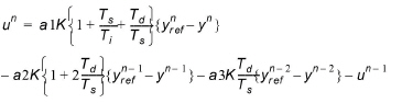
where:
- – un is the gate level (or discharge in case of a Direct discharge structure) at the nth time step,
- – K a factor of proportionality,
- – Ti the integration time,
- – Td the derivation time,
- – Ts the sampling period, i.e. the simulation time step,
- –

- is the required value of the target point at the nth time step,
- – yn the actual value of the target point at the nth time step,
- – a1, a2 and a3 are weighing factors. In this way {yref - y} represents a deviation from the desired situation. This deviation is minimized by the PID algorithm in (6.19).
- – The variables K, Td, Ti, a1, a2 and a3 are specified in the PID parameters menu.
The additional parameters below must be specified when the Control type is ‘PID’.
PID parameters. The set of PID parameters used in equation (6.19) is chosen here. These sets are defined in the PID parameter menu.
Setpoint type. This defines how the setpoint value is defined. The following options are available:
· Absolute value: the specified value in the ‘Setpoint’ field is an absolute value
· Time series: the time-varying absolute value of the setpoint is specified in a time series
· Tabulated: the absolute value is specified in a table, containing the relationship between an input variable defined by the Table input and the output which is identical to the desired setpoint
Control input. May also be known as the Process Variable in general PID definitions. The variable indicates the target variable, for which the deviation to the desired value is minimized using the PID equation (6.19). The ‘Edit’ button may be used to select e.g. a sensor or specify an expression.
Setpoint. The Setpont is the desired (target) value for a variable in the system. Examples are; Reservoir water level, minimum environmental streamflow, irrigation abstraction requirements etc. Setpoint defines the target value for the selected Setpont type. The setpoint can either be a numeric value or an expression. The ‘Edit’ button may be used to specify an expression.
Setpoint file. The time series containing the values for the setpoint.
Table input. Indicates the variable used as input in the table for the ‘Tabulated’ type. The ‘Edit’ button may be used to select e.g. a sensor or specify an expression.
Setpoint scale. The setpoint will be multiplied by this factor. The scale can either be a numeric value or an expression. The ‘Edit’ button may be used to specify an expression.
![]()