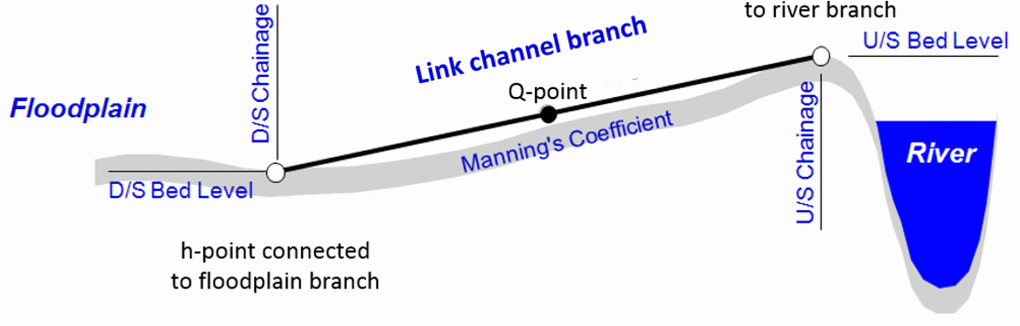
A branch may be defined as a ‘Link Channel’ (see Branch Type above), where a link channel typically is a short branch used to connect a flood plain to the main river branch and therefore generally represents the embankment geometry between parallel rivers (e.g. main river branch and flood plain branch). Link channels are modelled as a single structure branch of only three computational points (h-Q-h).
A link channel doesn’t require cross sections to be defined: the h-points are automatically assumed to be made of very wide geometries.
The Q-point in the middle of link channel branch is defined through an ‘open culvert’ type of structure. That is, an overflow weir with a length to include the friction loss component. The friction loss is computed using the length defined by the upstream and downstream chainages of the branch.
Typical link channels representation is illustrated in Figure 6.3.
Figure 6.3 Longitudinal representation of a link channel
Note: Following the internal formulation of the link channel where no true cross sections are defined in a link channel branch, the usage is restricted to Hydro-Dynamic simulations ONLY. Thus, for Advection-Dispersion, Water-Quality and Sediment-Transport calculations the set-up should be void of link channels. Link channels should therefore be replaced by ‘regular’ branches with actual cross sections defined and eventually a weir to describe embankment levels if this is what should be represented with the connecting branch.
Note: since a link channel do not contain cross sections, it doesn’t have storage capacity at nodal points where the link connects to another branch.
If a branch type is set to Link Channel, the Link Channels tab automatically appears and the following properties must be specified.
The link channel geometry comprises the definition of the longitudinal and transversal geometry of the embankment along the river. The geometry is defined from the following parameters:
Type
The Type describes the way the embankment geometry (transversal to the flow direction through the link channel) is defined. The following options are available:
· Depth-Width: the cross sectional geometry in the link channel is defined with a number of relationships between the depth above the upstream invert and the width of the channel.
· Level-Width: the cross sectional geometry in the link channel is defined with a number of relationships between the level and the width of the channel.
· Cross section DB (cross section database): the cross sectional geometry is read from a cross section specified in the ‘Cross sections’ menu.
Datum
The Datum may be used for adjusting the levels of the link channel, e.g. to conform with a specific reference datum in the model area or to conduct sensitivity tests. The datum value is added to upstream levels (either the Upstream invert for a Depth-Width type of geometry, or the levels from the table for a Level-Width type, or the cross section's bottom level for a Cross Section DB type) as well as to the Downstream invert.
Note that the ‘Cross section DB’ option the equivalent Datum value in the cross section definition is also taken into account.
Upstream invert
Upstream bed level of the link channel. Editable for the Depth-Width link channel type only. The 'Corrected invert' value shows the final value corrected with the Datum, which is used in the calculation of the Q/h relations.
Downstream invert
Downstream bed level of the link channel. The 'Corrected invert' value shows the final value corrected with the Datum, which is used in the calculation of the Q/h relations.
Depth/Level-Width table
This depth/level-width table defines the cross section geometry of the flow area in the link channel. Both the depth and the width must be increasing. This table is only active for ‘Depth-Width’ or ‘Level-Width’ link geometry types.
Branch name, TopoID and Chainage
When the link geometry type is set to ‘Cross section DB’, the branch name, TopoID and chainage of the cross section defining the geometry must be specified here.
Allow for recalculation
When this option is ticked, the values in the Q/h relations table may recomputed from the menu Run \ Recalculate flow conditions…
This option can be unticked in order to keep the Q/h relations table unchanged while recomputing other tables from the Run \ Recalculate flow conditions… menu.
No of Q/h relations
The number of relations to be used in the Q/h relations table is specified here. This number is only used when the geometry in the ‘Link geometry’ options is described with 8 levels or less.
If the geometry in the ‘Link geometry’ options is described with more than 8 levels, it is assumed that the cross sectional geometry is accurately defined and that the Q/ relations should be computed at the exact levels defining the geometry, therefore ignoring the specified ‘No of Q/h relations’.
Q/h Relations table
Free outflow Q/h relations must be calculated prior to the simulation. To calculate the Q/h relationships, specify the number of relationships required and press the ‘Calculate Q/h relations’ button. The result of the calculation will appear in the table.
Table values in the Q/h relations table can be changed if required but general recommendation is to leave the table as is from the automatic calculation when pressing the ‘Calculate Q/h relations’ button. Table parameters are:
· y: water depth in link channel structure
· Area: flow area in link channel structure
· Radius: hydraulic radius in link channel structure
· Conveyance: conveyance indicator in link channel structure
· Qc: critical flow in link channel structure
· hUS: water level in h-point upstream of link channel structure
· US Type: indicator of upstream flow type derived from the calculated flow parameters in the link channel (can not be changed)
· hDS: Water level in h-point downstream of link channel structure
· DS Type: indicator of downstream flow type derived from the calculated flow parameters in the link channel (can not be changed)
Note : If any of the parameters defining the link channel geometry or loss coefficients is changed, the Q/h relations must be re-calculated so that the change is taken into account in the simulation.
Type. The bed resistance along the length of a link channel can be described using Manning's M or Manning's n.
Value. Bed resistance value, expressed in the unit type selected above.
Positive flow and Negative flow. Head loss factors must be defined for Inflow (contraction), Outflow (expansion), Free overflow and Additional losses. All four factors are dimensionless and must be within the range 0.00 - 1.00. Each factor may be given a different value depending on the flow direction across the link channel.
![]()