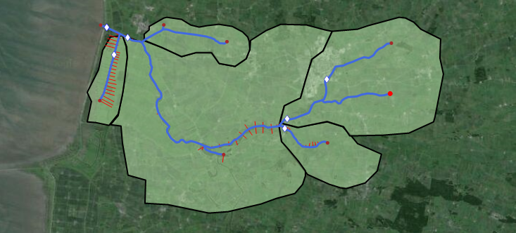
The River network forms the basis of all River applications. The river network is defined as a combination of connected river segments and computational points, and module specific features are then generally added to the model using the river network as a base (river network example illustrated in Figure 6.1)
Figure 6.1 Example of river network in MIKE HYDRO.
Additional river network details:
·
· River segments are called Branches and branch definitions include options for connecting river branches as well as defining User defined chainage points.
· Calculation points in the hydrodynamic module include h- and Q-points:
- – h-points: Water level (h) calculation points.
All Cross sections as well as start- and end-points of river branches automatically creates h-points in a model. Furthermore, h-points are automatically inserted to ensure that the maximum distance between h-points (grid spacing) is less than or equal to the length defined as the Maximum dx variable (see Grid spacing (p. 64))
- – Q-points: Discharge (Q) calculation points. Q-points are automatically inserted mid-ways between h-points in the entire model area.
Additionally, hydraulic structures are included as Q-points in the numerical model.
· Inflow to the River network is specified through Boundary conditions (see 12.1 Standard boundaries (p. 236)).
This chapter describes the following topics in further detail:
![]()