Structures are always located in Q-points in which the momentum equation is normally solved, and the reason for including a structure in a model is always to replace the momentum equation with something more suitable for the structure in question.
The effect of the bed friction is generally not taken into account thus it is required that the h-points (cross sections) up- and downstream are situated close to the structure.
Inserting a structure
Composite structures definition
Structure types definition
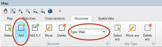
To insert a structure in the model first choose the relevant structure type in the Structures ribbon in Map view (see Figure 6.13).
Figure 6.13 Map view ribbon for inserting and editing hydraulic structures
Select the ‘Add’ button and digitise the desired location of the structure by clicking on one of the rivers in the setup.

Note: The structure must be located on a river branch.
Also note that the mouse cursor changes to a cross when the cursor is properly placed.
To insert a structure at a specific geographical location select ‘Add X, Y’ and specify the coordinates using the map coordinate system. If specified location is not located on a branch the structure will be placed at the closest valid location.
Alternatively, structures can be inserted in the river network in Tabular view, where their properties can be specified. To add or remove a structure in Tabular view, use the ‘Append’ and ‘Delete’ buttons


at the bottom of the page. The table is synchronized with the attributes on top of the page, so the properties of the structure can be entered either in the table or at the appropriate dialogues of the tabular view.
To display the properties of a specific structure to the Property view, select the checkbox of that item in the table. More than one item can be selected at a time. When several table items are checked, it is possible to unselect all of them simultaneously by clicking on the ‘Clear selection’ button

.
Composite structures definition
Composite structures are easily defined using an approach of combining a number of individual structure types. A composite structure such as a bridge with several openings and possible occasional road overtopping can be defined as a combination of multiple culverts and an overflow weir. The only requirement for creating a composite structure is, that all individual structures in the composite structure is defined at the exact same location (same River Name and Chainage). This example is illustrated in Figure 6.14.
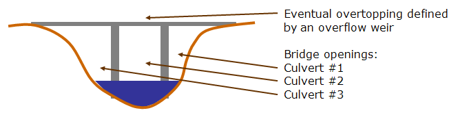
Figure 6.14 Composite structure illustration. Can be defined with a number of individual structures defined at exact same location.
One of the benefits of defining a composite structure as illustrated above is, that it is possible to obtain and analyse flow results through/over each of the individual structures forming the composite structure.
Most hydraulic structures available can be defined as one of three different types; ‘Regular’, ‘Side Structure’ or ‘Side structure with storage’.
Regular
Regular structures are internal structures that specify a flow in the branch typically based on up- and down- stream flow conditions.
Side structure
Side structures are special type of a regular structure. Side structures takes water out of the river network at the location where the side structure is defined.
Internally in the calculation engine, side structures are handled through an automatic generation of an ‘artificial’ side branch with the side structure included as a regular structure placed midway in the side branch as illustrated in Figure 6.15.
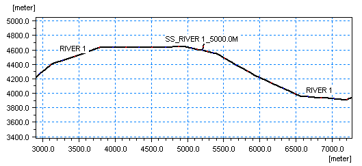
Figure 6.15 Illustration of automatically generated side structure branch
Specific characteristics of a Side Structure includes:
· Head losses are excluded from the flow calculation for side structures by setting internally the flow areas of the cross sections in the side structure branch as extremely large (1xe20 m2) and hence, the velocity component in these sections (V=Q/A) is a negligible number.
· For culverts and weirs, an assumption of free out- and over-flow respectively is implemented through an internally defined water level boundary condition for the outflow point of the artificial side structure branch. The boundary condition is defined as a water level boundary with a low water level.
· Naming convention used for the artificial side branch are: “SS_”<original branch name>”_”<original chainage>
· In case of multiple side structures defined at the same location, these will all be included in the same side branch as a ‘composite side structure’.
· A side structure branch is a simple h-Q-h branch with two cross section h-points in each end of the branch and a structure in the centre Q-point.
· Up- and downstream cross sections in the Side Structure Branch are automatically assigned with a shape identical to the main river cross section located immediately downstream of the side structure location. Upstream cross section of the Side Structure branch is identical to the section in the main river, but the downstream section has been shifted 10 m down in order to obtain a free outflow condition in the Side Structure. See Figure 6.16.
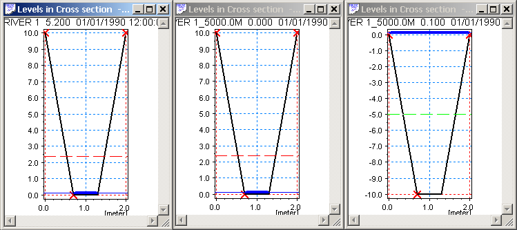
Figure 6.16 Cross sections as defined in the artificial Side Structure branch. Left part illustrates the cross section in main river downstream of the chainage defining the Side Structure. Middle part illustrates the upstream cross section at chainage 0 of the side structure branch (=copy of main branch section) and right part illustrates the downstream cross section of the Side Structure Branch, which is identical shape as the other sections but only shifted -10 m.
Side Structure with Storage
Including side structures with storage in a branch results in automatic generation of a side branch with the structure placed midway as described for side structures without storages. In addition to this, the downstream cross section of the side structure branch has a user-defined, additional storage area (reservoir). The significant difference between a structure defined as ‘Side structure’ and ‘Side structure with storage’ is, therefore, that in the latter case, the water conveyed through the side structure is stored in the system, the reservoir storage can be continuously measured and water from the storage can potentially return to the main river through the side structure in case water levels in storage gets higher than the water level in the river. For the structure type without the storage, the water simply leaves the river model and disappears completely.
When using a side structure with reservoir an additional tab ‘Storage’ will appear next to the ‘General’ tab for specification of reservoir details.
Storage capacity type. The storage capacity type of the reservoir must be defined using the drop-down menu. There are two options:
· Elevation-area: Additional storage area is derived directly from the Elevation-Area relationship by using the water level in the reservoir. An Elevation-Area relationship is specified by entering corresponding values of Elevation and Area in the table. Click the Append button to add a row to the table.
· Elevation-volume: Additional storage area is calculated by using the Elevation-Storage volume relationship and the following formula:
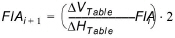
where:
FlA: Flooded or additional storage area at level ‘i’ or ‘i+1’

and

are differences in volumes and levels respectively from values defined in the Elevation-Storage volume table.
Initial surface area. The initial surface area must be defined if Elevation-volume storage capacity type is selected.
Apply Coordinates. The Apply coordinates offers a possibility for defining coordinates for the reservoir - which in the case of the artificially generated side structure branch is identical to the end point of the side structure branch.
Additional specific features of the Side Structure with Reservoir:
· Head losses are excluded from the flow calculation for side structures with reservoir by setting internally the flow areas of the cross sections in the side structure branch as extremely large (1e20 m2) and hence, the velocity component in these sections (V=Q/A) is a negligible number.
· The boundary introduced through the inclusion of the side structure is internally specified as a no flow boundary. Flow may be included through specification of point source boundaries at the boundary.
· More side structures with reservoir in the same location will result in one side branch for each.
· The side branches will be named with the naming convention: “SSPR”<original branch name>”_”<original chainage>”_”<Structure ID>.
· The cross sections applied in the artificially generated Side Structure Branch with Reservoir are defined such that the upstream cross section is a copy of the section in the main river downstream of the chainage defining the side structure and the downstream cross section is defined as a triangular cross section shape as illustrated in Figure 6.17.
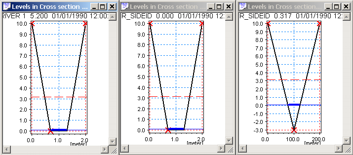
Figure 6.17 Cross sections as defined in the artificial Side Structure with Reservoir branch. Left section illustrates cross section in main river downstream of chainage defined for Side Structure. Middle section illustrates the upstream section of the side structure branch (copy of main branch section) and right section illustrates triangular section applied at downstream h-point of Side Structure Branch.
Levels of the cross section is adapted from the defined Level-Area/Volume table, whereas the widths (0 m at bottom and 100 m in top of section are just artificial numbers applied in order to draw a cross section in result presentation tools. The calculated storage volume of the section is defined from the table-values.
Structure geometry definition
Some of the available structure types require a Structure Geometry definition to complete the structure input. These include the Weir and Culvert structure types.
It is important to notice, that the Structure Geometry to be defined is the geometry - or level-width relation - of the sections of the hydraulic structure where the water can potentially flow. That is, the Flow Area definition as illustrated in Figure 6.18 marked with the blue section.
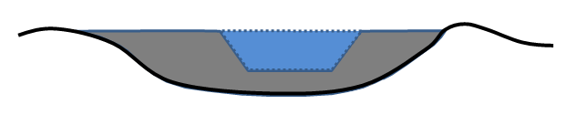
Figure 6.18 Illustration of Structure Geometry definition. The blue area which potentially conveys water over/through the structure is the geometry which must be defined.

Example: Assuming the following geometrical definition of the blue flow area in Figure 2.36: Crest level of structure is at level 3 m (crest level = bottom of blue area in figure), bottom width is 5 m, top-width is 7 m at a level of 5 m. A structure geometry definition in this case is normally defined as presented in Table 6.1 below.
|
Level [m] |
Width [m] |
|---|---|
|
3.00 |
0.00 |
|
3.05 |
5.00 |
|
5.00 |
7.00 |
Structure plotting
For structures where specification of dimensions and elevations is part of defining the structure, it is possible to make a plot of the structure together with the upstream and downstream cross section. This includes all weirs, culverts and gates. Plotting structures and their neighbouring cross sections together helps ensuring that structure dimensions and elevations are specified correctly.

Note: A typical source of model instability is a structure which is larger or lower than the neighbouring cross section.
For structures which can be plotted the dialogue contains a section named ‘Graphics’ with a ‘Plot/Refresh’ button. Clicking this will open a separate graphical window showing two plots. The left plot being the upstream cross section and the structure, and the right plot being the downstream cross section and the structure. Initially, the centre of the structure is horizontally aligned to marker 2 of the cross section.
The following figure shows a typical structure plot for a weir.
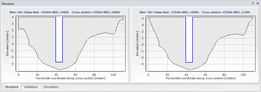
Figure 6.19 Structure Plot
![]()