A special numerical treatment can be applied to two types of infrastructures in the 2D domain: buildings and roads. The spatial extent of buildings and roads is defined by zones. A zone is a series of polygons from a GIS layer, all being applied the same properties. Zones are therefore used as categories of buildings or roads.
The topography in the 2D domain should be given as natural ground level and for buildings and roads it is possible to specify a correction of the topography. A special treatment of the flux across faces on the borders of buildings and roads is also applied in the simulation.
Three types of file format can be used for defining the zones:
· shape file
· dfs2 or dfsu file
· XYZ file.
For XYZ files and shape files, the zones are defined as the closed region within a number of polygons. For dfs files, the zones are defined by a map identifying the location of the different zones. Each zone is identified by an integer number larger than zero. If there are overlapping zones for the two types of zones and/or with land cover zones (e.g. specified for 2D surface roughness definition), the priority is: Building, road and land cover. If an element from the 2D domain belongs to more than one polygon in the XYZ file or the shape file, the information from the last polygon read from the file is applied.
For dfs files, the value should be zero in areas with no building or road.
For XYZ files, the data in the file must be formatted as ASCII text in five columns with the two first columns giving the x-and y-coordinates of the points. The third column represents connectivity. The connectivity column is used to define arcs. All points along an arc - except the last point - shall have a connectivity value of 1 and the last point shall have a connectivity value of 0. The fourth column contains the z-value at the point. Finally, the fifth column contains the zone number. The z-coordinate is only used when the XYZ file is used to define building zones. Here the Z-value must contain the height of the buildings or the level of the top of the buildings.
Note that the 2D domain mesh / grid elements don't have to be aligned with the zones polygons: the zones will automatically be mapped to the nearest element faces. The use of 2D infrastructures can therefore avoid meshing buildings with very small mesh elements, which improves model stability; but the mesh should not be too coarse compared to the buildings size in order to correctly take these buildings into account.
The use of 2D infrastructures is particularly suited when applying rainfall on the 2D domain because the volume of rain falling on buildings remains accounted for (as opposed to when buildings are excluded from the mesh / grid), and the effect of the buildings on the flow is also included.
General description
The flux across an infrastructure face - a building face or a road face - is calculated using an empirical formula or the flow equations depending on the surface elevation. A face in the 2D mesh is defined as building face, if the element to one side of the face belongs to a building zone and the element to the other side belongs to a road zone or to none of the zones. Also, a face where the elements on both sides of the face belong to a building zone and where there is a difference in the level of the buildings, is defined as a building face. A face in the 2D mesh is defined as road face, if the element to one side of the face belongs to a road zone and the element to the other side belongs to none of the zones.
The structure level for an infrastructure face is defined as the maximum of the level for the two elements on each side of the face. If the water level in both elements on each side of the infrastructure face is above the structure level, the flow equations are applied and otherwise the empirical formula is applied. If a building zone is excluded from the calculation the flux across the corresponding building faces are always zero and the elements in the zone are treated as dry elements.
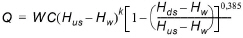
The discharge, Q, over a section of the infrastructure corresponding to an element face with the length (width), W, is based on a standard weir expression, reduced according to the Villemonte formula:
(3.4)
where Q is discharge through the structure, W is width, C is weir coefficient, k is the weir exponential coefficient, Hus is upstream water level, Hds is downstream water level and Hw is the structure level. The value of the weir exponent is 1.5 and the default value of the weir coefficient is 1.838.
When 'Include building zones' has been selected, the following items must be specified:
· Layer: The source layer defining the building zones
· Zones attribute / item: For a shape file or dfs file, this is the attribute or item in the file containing the integer number, used to identify the zone each polygon belongs to.
· Map projection: For a XYZ file, this is the map projection in which the XY coordinates in the file are defined.
· Height type: Using a XYZ file or a shape file, buildings heights can either be defined as a relative height above ground level or as an absolute elevation. Using a dfs file, the height of a building is specified by the level of the top of the building.
· Height definition: Buildings heights, controlling the correction of the topography, can either be uniform (same height for all zones) or read for each zone from the source layer.
· Height attribute / item: This is the attribute / item in the source file containing the height value for each zone, when the height is read from the source layer.
· Zones table: For each of the zones, it is required to specify:
- Zone ID: Zones are initially named using the corresponding integer number in the source layer, but it is possible to rename the zone to more appropriate names.
- Include: It is possible to specify if the building should be included or excluded from the calculation. If the buildings are excluded, the building elements will be treated as dry elements.
- Uniform height / elevation: The relative height or absolute elevation of the buildings in the zone. When using relative heights, you must specify the height of the buildings as the distance from the natural ground level to the highest point of the building. The top level of the building is then calculated from the maximum ground level in the area of the building. When using absolute elevations, the height of the building is specified as the top level of the building.
- Discharge coefficient: For each building zone you also have to specify a discharge / runoff coefficient. This coefficient must be larger or equal to zero and lower or equal to one. The coefficient is multiplied to the flux across a building face.
· Dampening delta depth: When the water level gradient across a structure is small, the corresponding gradient of the discharge with respect to the water levels is large. This in turn may result in a very rapid flow response to minor changes in the water level upstream and downstream. As a way of controlling this effect, a dampening delta depth has been introduced. This depth is a critical water level difference below which the discharge gradients are suppressed. The default value is 0.01 meter. If a structure shows oscillatory behaviour it is recommended to increase this value slightly.
· Weir coefficient: The weir coefficient used to compute the discharge through the building face.
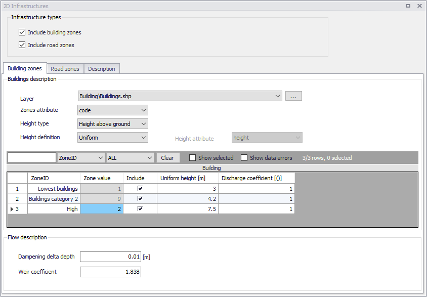
Figure 3.25 Defining building zones from a shape file layer
When 'Include road zones' has been selected, the following items must be specified:
· Layer: The source layer defining the road zones
· Zones attribute / item: For a shape file or dfs file, this is the attribute or item in the file containing the integer number, used to identify the zone each polygon belongs to.
· Map projection: For a XYZ file, this is the map projection in which the XY coordinates in the file are defined.
· Offset definition: Using dfs files, roads' offset - controlling the correction of the topography - can either be uniform (same offset for all zones) or read for each zone from the source layer. Using a XYZ file or a shape file, the offset can only be specified as a constant value for each road zone.
· Zones table: For each of the zones, it is required to specify:
- Zone ID: Zones are initially named using the corresponding integer number in the source layer, but it is possible to rename the zone to more appropriate names.
- Uniform offset: The offset for each road zone, when using a uniform offset.
· Dampening delta depth: When the water level gradient across a structure is small, the corresponding gradient of the discharge with respect to the water levels is large. This in turn may result in a very rapid flow response to minor changes in the water level upstream and downstream. As a way of controlling this effect, a dampening delta depth has been introduced. This depth is a critical water level difference below which the discharge gradients are suppressed. The default value is 0.01 meter. If a structure shows oscillatory behaviour it is recommended to increase this value slightly.
· Weir coefficient: The weir coefficient used to compute the discharge through the road face.
Description
Use the Description tab to add free text descriptions for buildings and roads.
![]()