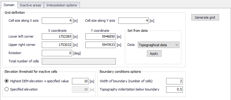
Figure 3.6 The Domain tab for configuring new rectangular grids in MIKE+
· Grid definition: Define the grid cell size along the x- and y-directions, and the extent of the 2D model domain. The extent may also be derived from available data layers, such as:
- Topographical data. Based on the data layer(s) to be used in 2D topography interpolation. The data layers must be activated in the Interpolation Options tab to be properly detected as ‘Topographical Data’.
- Collection system network. The extent of the whole collection system model.
- Active selection. The maximum extent of currently-selected model elements.
· Elevation threshold for inactive cells: Define the elevation value over areas that should remain inactive during 2D model computations. Inactive grid cells are excluded from computations.
- Highest DEM elevation + specified value. The specified value is added to the maximum elevation value detected from the 2D domain file.
- Specified elevation. Areas with terrain levels equal to or higher than the defined value are considered inactive.
· Boundary conditions options: Specify the width and grid cell levels at 2D boundary sections. 2D boundaries (i.e. closed and open boundaries) are located along edges of the 2D domain in MIKE+.
- Width of boundary (number of cells). Define the width (in the direction transversal to the border of the domain) of 2D boundary edges in terms of number of grid cells. Grid size is defined under the ‘Grid definition’ section. This width is used for the indentation described below.
- Topography indentation below boundary. The depth subtracted from the lowest cell level within the area with indented cells. The adjusted level in this lowest level is assigned to all other cells in the open 2D boundary area (Figure 3.7). This is used to apply a constant topography along the boundary and ensure that the boundary is e.g. always flooded.
Along the 2D model perimeter where no 2D boundary condition is applied, the ground elevation is automatically raised to the elevation threshold for inactive cells. This is to represent a closed boundary ensuring zero flow across the perimeter (also see the Raised areas in Figure 3.7).
Along stretches where an open water level or discharge boundary is defined, the ground is lowered to a uniform level to ensure valid numerical computations at the boundary as open boundaries must be wet all the time (Figure 3.7).
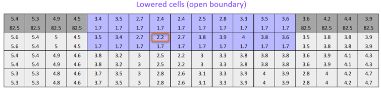
Figure 3.7 Example of automatic terrain level lowering along an open 2D boundary spanning 10 2D cells. In each 2D cell the original levels (upper values) and adjusted levels (lower values) are shown. The value of 1.7 m is taken from the lowest-level unadjusted cell in the area (i.e. 2.2 m encircled) minus the specified indentation (here 0.5 m).
![]()