Modelling real network elements
When setting up a model some knowledge of the principles used in the numerical solution of the flow equations is useful. This section will provide some information, for further please refer to the “MIKE 1D Reference Manual”.
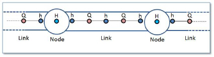
In all pipes and canals the computational grid is set up in an alternating sequence of h- and Q-points. In these grid points the discharge Q and water level h, respectively, are computed at each time step. The links (pipes and canals) will always be setup with h-grid points at each end where the link connects to nodes in the network. This means that links will always have an odd number of computational grid points with three points ( h - Q - h ) as the minimum configuration.
Figure 3.1 The computational grid
The nodes will only have a single computational point where the water level H is computed. The nodes are typically circular manholes in the sewer network. But it can also be basins or tanks with a significant volume. Still only a single water level computational point is located at the node. Based on the computed water level and the description of the geometry of the node the computation keeps track of the volume of water stored in the node.
It is of importance to notice that only a water level is computed at the nodes. In the simple case with one incoming pipe to a node and one outgoing pipe it may seem simple to compute a "flow through" the node. But think of the more complex situations with more than two pipes connected and also external flow entering the node. Defining a "flow through the node" is in the general situation not possible.
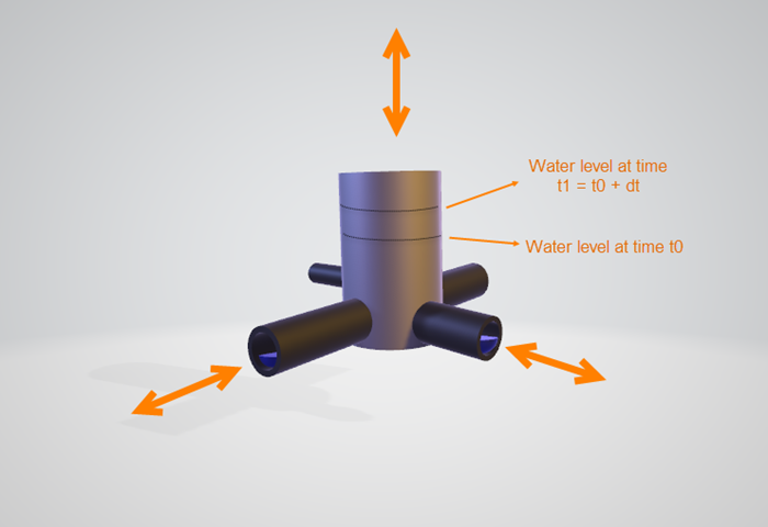
Figure 3.2 Water flowing through a node
At the nodes the water level is computed based on the water level at the previous time step and the flow contributions during the time step from each connected pipe and external connected flow like a catchment runoff discharge. When the computational grid is set up for a network of links and nodes it will end up like shown in Figure 3.3.
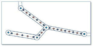
Figure 3.3 The computational grid for a given network
MIKE1D is able to handle various “devices” which basically are related to manholes, basins, soakaways or other constructions in the sewer network. These devices are: pumps, weirs, orifices, valves and storm water inlets. Typically these elements are placed at locations which in the real system could be manholes, basins or other structures. It is also characteristic for all mentioned elements that there will be a discharge computed for the device: pump discharge, discharge over weir, flow through orifice and flow through valve.
The main point to realize is the conflict between computing a discharge for these elements and the fact that only a water level is computed at nodes.
This is why the pump, weir, orifice, valve and storm water inlet elements from the computational and numerical point of view are links and not an element placed in one node. All the elements are links forming a connection between two nodes.
In MIKE+ we have five functional elements which from the model building point of view are related to nodes like manholes or basins. These are pumps, weirs, valves, orifices and storm-water inlets. The concept of elements related to nodes is reflected in the design of the dialog for editing the parameters for these elements. Here you find a field named "From" for all of the elements. The field takes the ID of a node as input. All elements also have a field for "To:" which also takes a node ID as input.
Seen from the computational solution point of view the five elements are actually connections from one node to another node. This is similar to how pipes are defining the link for flow between nodes as reflected in the dialog where you find fields for entering "From node:" and "To node:".
![]()