
Definitions
Branch name
Name of the actual river branch.
Topo ID is an abbreviation of ‘Topographical Identifier’, which refers to the data defined in the Cross section file (xns11). The cross section file offers the possibility to store several measurement campaigns (e.g. from different years or before and after the construction of a bridge structure). The main purpose of this Topo ID is to ease the implementation of an alternative scenario simulation once the river model has been properly defined. As it is normally a sound assumption to say, that the river digitization and length, etc. does not change then it is possible to change the topographical data used in a simulation simply by changing name of the Topo ID for one or more river branches (and eventually save the nwk11 with a different name than the original file).
Note that the String defined for the Topo ID must be identical to a Topo ID present in the cross section file for the actual river branch. If not, the calculation can not be performed.
Upstr. Ch.
The chainage of the first point in the branch.
In case the chainage value of this point should be adjusted it must be changed in the ‘Points’ property page.
Downstr. Ch.
The chainage of the last point in the branch.
Again, in case the chainage value of this point should be adjusted it must be changed in the ‘Points’ property page.
Flow Direction
Indicator for how MIKE 11 should interpret the chainage definition with respect to the natural flow direction. The default assumption of MIKE 11 is to define flow direction positive with increasing chainages looking downstream of the river.
If flow direction is selected as positive, the simulated discharges will be positive when the flow direction is from upstream chainage to downstream chainage. Vice versa if the flow direction is defined as negative.
Hence, a river survey with river chainages starting with 0 at the river mouth and chainages increasing upstream should be defined as a ‘Negative Flow’ branch as illustrated in.
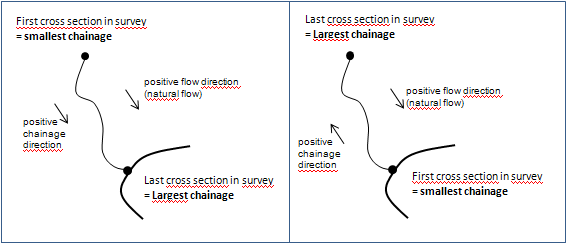
Figure 2.34 Illustration of flow direction definition. Left figure illustrates situation where increasing chainages follow positive flow direction and branch should therefore be defined as ‘Positive Flowdir’ whereas the right part of the figure illustrates the situation where a survey has increasing chainages from the river outlet and upstream. This situation requires the river branch to be defined as ‘Negative Flowdir’
Maximum dx is the maximum grid-spacing (or distance) allowed by the calculation engine between two adjacent h-points (water level calculation points). At locations where Cross sections are present in the cross section file, the calculation engine will always create h-points at these location and in case the Maximum dx is defined with a value smaller than the distance between cross sections, the calculation engine will automatically insert a number of additional calculation points by interpolation in between existing cross sections such, that the maximum distance between h-points in the calculation will less than or equal to the defined value of Maximum dx.
Hence, the Maximum dx parameter is a possibility for increasing the spatial resolution of the river model by forcing an additional number of calculation points in between physically defined cross sections in the cross section file.
Branch Type
· Regular:
A ‘normal’ branch composed by a number of calculation points defined from cross sections. A minimum of one cross section is required
· Link Channel:
No cross sections are required. Instead the parameters given in the Link channel dialog must be specified using the The ‘Edit Link Channel Parameters...’ button button.
Note that LINK channels are ONLY to be used when conducting Hydrodynamic simulations.
· Routing:
A special routing feature is available in the network branch definition in case a special module is present in the MIKE 11 license. This feature has been developed as part of a dedicated Japanese version of MIKE 11 and hence only applicable if a special M11-Japanese module is purchased and added to the MIKE 11 license.
The Routing option in the branch type column of the Branches dialog as well as the ‘Routing’ option in the tree view as described in section 2.4, is only visible to users holding the required special module in their license.
No cross sections are required. Only the flow is calculated, no water levels. See section 2.4 Tabular view: Routing (p. 149).
· Kinematic Routing:
Kinematic Routing can be used to model the hydraulics of upstream tributaries and secondary river branches, where the main concern is to route water to the main river system. The Kinematic Routing method does not facilitate the use of structures at Kinematic Routing branches. Moreover, the method does not account for backwater effects.
At Kinematic Routing branches, it is possible to run the model without information on cross-sections. In turn, this indicates that Kinematic Routing branches can not be used to model a looped part of a river network. Employment of Kinematic Routing branches requires that all branches located upstream of a Kinematic Routing branch are defined in the same way.
· Stratified - no longer available:
![]()