Setting up a saturated zone hydraulic model based on the 3D Finite Difference Method involves defining the:
· the geological model,
· the vertical numerical discretisation,
· the initial conditions, and
· the boundary conditions.
In the MIKE SHE GUI, the geological model and the vertical discretisation are essentially independent, while the initial conditions are defined as a property of the numerical layer. Similarly, subsurface boundary conditions are defined based on the numerical layers, while surface boundary conditions such as wells, drains and rivers (using MIKE Hydro River) are defined independently of the subsurface numerical layers.
The use of grid independent geology and boundary conditions provides a great deal of flexibility in the development of the saturated zone model, thus the same geological model and many of the boundary conditions can be re-used for different model discretisation and different model areas.
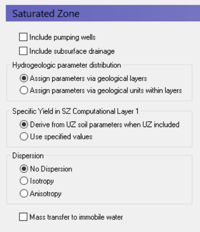
Include Pumping wells
By default, wells are not included, but in most applications pumping wells play a major role in the hydrology of the area. If wells are included in the model, then this must be checked and a new item in the data tree appears where the well database can be defined.
Include Subsurface drainage
Subsurface drainage is used to limit the amount of groundwater that reaches the ground surface and to route near surface groundwater to local streams and rivers. There are a number of drainage options for specifying surface drains in MIKE SHE, which are described in more detail in the section Drainage.
Hydrogeologic parameter distribution
The first option allows you to specify the hydrologic parameters of the geologic layers and lenses directly by means of .dfs2 grid files, point/line theme .shp files, or irregular xyz point values. The second option allows you to assign the hydrologic parameters to the geologic layers by means of zones with uniform properties, whereby the zones are defined by integer grid codes.
Specific Yield in SZ Computational Layer 1
By default, the specific yield in the top SZ layer is calculated from the specified UZ field capacity and saturated water content in the UZ layer that contains the initial water table. This is done to ensure the consistency between the SZ specific yield and the UZ properties. If these are inconsistent, then you may have a situation where the change in water table elevation in the UZ and the SZ models will be different.
You must specify a Specific Yield value for every SZ layer including the top SZ layer. However, when a UZ model is included in MIKE SHE, by default this value is not used. The Use specified values option allows you to over-ride the default. This may be a useful option to invoke if, for example, you are using Autocalibration. In this case, you can define and optimize the Specific Yield directly.
Dispersion
If your simulation includes water quality modelling in the saturated zone, then you must also define the type of dispersion you want to simulate. Dispersion is the physical process that causes solutes to spread longitudinally, vertically and horizontally as they move through the soil. The dispersion essentially represents the natural, microscopic variations in pore geometry that cause small scale variations in flow velocity.
No dispersion - Dispersion is ignored and no dispersivities need to be specified.
Isotropic - The transverse horizontal and transverse vertical dispersivities are assumed to be the same. Only two dispersivities need to be specified - the longitudinal and the transverse dispersivities.
Anisotropic - The horizontal and vertical transverse dispersivities are different, which requires the specification of five different dispersivities.
Mass Transfer to Immobile Water
If many cases, immobile water trapped in the bulk soil matrix is both a source and sink of solutes. In other words, as solutes move in the bulk water media, some of the solutes will diffuse into water trapped in the pores of the soil grains.
Furthermore, solutes in fractured media will be transported by diffusion in and out of the soil matrix. The porosity of the soil matrix is often at least ten times less than the fractures. The diffusion of solutes into the soil matrix will retard the initial breakthrough of the solute and the matrix will act as a long term sink as the solute slowly diffuses out of the matrix long after the main solute plume has passed by.
If you turn on this option, then four additional data items may be required, namely
· the Secondary Porosity (V1 p. 312) will be added as a geologic property,
· a Dual Porosity transfer coefficient (V1 p. 316) per species will be required for each Water Quality layer,
· a Macropore/Secondary Half Life (V1 p. 351) coefficient will be required for each species to calculate the solute decay in the matrix, and
· an initial concentration in the matrix for each species.
Note: there is no separate sorption process for the immobile water.
Related Items:
· Saturated Flow - Technical Reference (V1 p. 597)
· Solute Transport in the Saturated Zone (V1 p. 663)
![]()