Saturated zone drainage is a special boundary condition in MIKE SHE used to defined natural and artificial drainage systems that cannot be defined in MIKE Hydro River. It can also be used to simulate simple overland flow in a lumped conceptual approach. Saturated zone drainage is applied to the layer of the Saturated Zone model containing the drain level. Water that is removed from the saturated zone by drains is routed to local surface water bodies.
Drain flow is simulated using an empirical formula. Each cell requires a drain level and a time constant (leakage factor). Both drain levels and time constants can be spatially defined. A typical drainage level is 1m below the ground surface and a typical time constant is between 1e-6 and 1e-7 1/s.
MIKE SHE also requires a reference system for linking the drainage to a recipient node or cell. The recipient can be a river node, another SZ grid cell, or a model boundary. Whenever drain flow is produced during a simulation, the computed drain flow is routed to the recipient point using a linear reservoir routing technique.
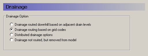
Drainage routed downhill based on adjacent drain levels
This option was originally the only option in MIKE SHE. The reference system is created automatically by the pre-processor using the slope of the drains calculated from the drainage levels in each cell.
Thus, the pre-processer calculates the drainage source-recipient reference system by
1. looking at each cell in turn and then
2. look for the neighbouring cell with the lowest drain level.
3. If this cell is an outer boundary cell or contains a river link, the search stops.
If the cell does not contain a boundary or river link, then the next search is repeated until either a local minimum is found or a boundary cell or river link is located.
The result of the above search for each cell is used to build the source-recipient reference system.
If local depressions in the drainage levels exist, the SZ nodes in these depressions may become the recipients for a number of drain flow producing nodes. This often results in the creation of a small lake at such local depressions. If overland flow is simulated, then the drainage water will become part of the local overland flow system.
Note: Be aware that the drainage is routed to a destination. It does not phyisically flow downhill. The drain levels are only used to build the drainage source-recipient reference system. In other words, any drainage that is generated at a node, is immediately moved to the recipient node. The assumption here, is that the time step length is longer than the time it takes for the drainage to reach its destination.
Drainage routing based on grid codes
This method is often used when the topography is very flat, which can result in artificial depressions, or when the drainage system is very well defined, such as in agricultural applications.
In this method, the drainage levels and the time constants are defined as in the previous method and the amount of drainage is calculated based on the drain levels and the time constant.
If the drainage routing is specified by Drain Codes, a grid code map is required that is used to restrict the search area for the source-recipient reference system. In this case, the pre-processer calculates the reference system within each grid code zone, such that all drainage generated within one zone is routed to recipient nodes with the same drain code value.
When building the reference system, the pre-processor looks at each cell and then
1. looks for the nearest cell with a river link with the same grid code value,
2. if there is no cells with river links, then it looks for the nearest outer boundary cell with the same grid code,
3. if there are no cells with outer boundary conditions, then it looks for the cell with the same grid code value that has the lowest drain level.
The result of the above search for each cell is used to build the source-recipient reference system.
The above search algorithm is valid for all positive Drain Code values. However, all cells where
Drain Code = 0 - will not produce any drain flow and will not receive any drain flow, and
Drain Code < 0 (negative) - will not drain to river links, but will start at Step 2 above and only drain to either a outer boundary or the lowest drain level.
Choosing this method, adds the Option Distribution item to the data tree. With the Option Distribution, you can specify an integer grid code distribution that can be used to specify different drainage options in different areas of your model.
Code = 1 - In grid cells with a value of 1, the drainage reference system is calculated based on the Drain Levels.
Code =2 - In grid cells with a value of 2, the drainage reference system is calculated based the Drain Codes.
Code = 3 - Drainage in grid cells with a value of 3 is routed to a specified Branch and chainage. At the moment, this option requires the use of Extra Parameters (V1 p. 347) and is described in SZ Drainage to Specified MIKE Hydro River H-points (V1 p. 758).
Code = 4 - Drainage in grid cells with a value of 4 is routed to a specified MOUSE man hole. At the moment, this options requires the use of Extra Parameters (V1 p. 347) and is described in the section Using MIKE SHE with MIKE URBAN (V1 p. 647).
Drain flow not routed, by removed from model
The fourth option is simply a head dependent boundary that removes the drainage water from the model. This method does not involve routing and is exactly the same as the MODFLOW Drain boundary.
Related Items:
· Groundwater drainage (V1 p. 61)
· Time varying SZ drainage parameters (V1 p. 761)
· Saturated Zone Drainage (V1 p. 610)
· SZ Drainage to Specified MIKE Hydro River H-points (V1 p. 758)
· Using MIKE SHE with MIKE URBAN (V1 p. 647)
![]()