Using MIKE SHE with MIKE URBAN
Coupling MIKE URBAN and MIKE SHE allows you to simulate the effect of urban drainage and sewer systems on the surface/subsurface hydrology.
The use of the integrated MIKE SHE/MIKE URBAN system is not very different from establishing a stand-alone MIKE URBAN model and a stand-alone MIKE SHE model. In principle there are three basic set-up steps to have a coupled MIKE SHE-MIKE URBAN model:
1. Establish a MIKE URBANMIKE URBAN hydraulic model as a stand-alone model, make a performance test and, if possible, a rough calibration using prescribed inflow and boundaries.
2. Establish a MIKE SHE model that includes the overland flow component and (optionally) the saturated zone and unsaturated zone components.
3. Couple MIKE SHE and MIKE URBAN by defining the locations where MIKE URBAN should interact with MIKE SHE.
When MIKE SHE runs, it will call MIKE URBAN and ask it to perform a MIKE URBAN time step. If the end of the MIKE SHE time step has not yet been reached, MIKE SHE will ask MIKE URBAN to calculate the next MIKE URBAN time step. The MIKE URBAN model will run normally if it is launched directly from MIKE URBAN.
Note: The MIKE URBAN coupling was originally developed for the stand-alone sewer modelling product called MOUSE, which was later incorporated into MIKE URBAN. Thus, references in this chapter to MIKE URBAN can largely be substituted by “MOUSE”. Further, older MOUSE models can be coupled to MIKE SHE using the same method described here.

Important: In the command lines in the input files, the word “mouse” must still be used. For example, the Extra Parameters option to activate the MIKE URBAN coupling must be “mouse coupling”.
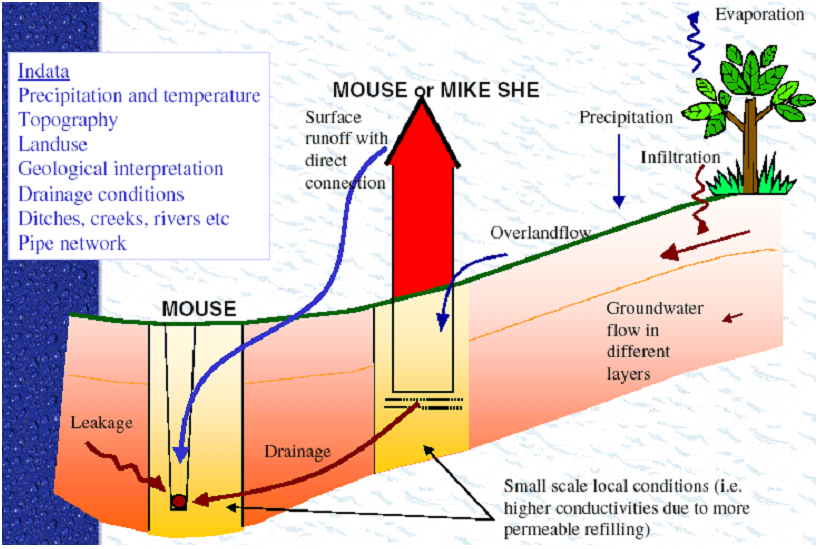
Figure 32.1 MIKE SHE to MIKE URBAN coupling linkages
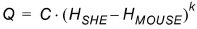
The exchange between MIKE URBAN and MIKE SHE is calculated based on the following equation
where Q is the exchange between MIKE URBAN and MIKE SHE, C is the exchange coefficient, k is a head difference exponent and
(32.2) 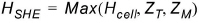
(32.3) 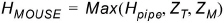
where Hcell is the head in the MIKE SHE cell, Hpipe is the head in the MIKE URBAN pipe, ZT is the topographic elevation in the cell and ZM is the elevation of the manhole.
There are five variations on how to calculate the exchange based on above equations:
MIKE SHE SZ to MIKE URBAN LINKS
This is a leakage-based solution in which the head difference exponent is 1 and the exchange coefficient in Equation (32.1) for the flow to or from the pipe is calculated by
(32.4) 
where CL is the leakage coefficient (see below), Pw is the wetted perimeter for the flow (see below), and L is the length of the MIKE URBAN pipe (link) in the MIKE SHE cell.
Leakage Coefficient - The leakage coefficient can be defined in two ways.
Option 1 is the simple method, which is to use the pipe leakage coefficient specified in the MIKE URBAN .ADP file. See Telling MIKE URBAN that it is coupled to a MIKE SHE model (V1 p. 651).
Option 2 uses a combination of the pipe leakage coefficient and the aquifer hydraulic conductivity. In this case, the leakage coefficient is calculated as a series connection of the pipe leakage coefficient (Cp) and the “average” leakage coefficient of the aquifer grid cell (Caq). The average leakage coefficient of the grid cell is calculated assuming that the exchange of water between the pipe and the grid cell is both vertical and horizontal. The leakage coefficient calculation does not calculate a detailed flow path based on a geometric calculation, since a MIKE URBAN pipe can be located anywhere in a grid cell. Instead, an average vertical and horizontal flow distance is used based on 1/4 of the vertical and horizontal cell dimensions. Thus,
(32.5) 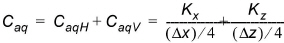
where Kx and Kz are the horizontal and vertical hydraulic conductivities respectively and Dx and Dz are the horizontal and vertical cell dimensions.
The final leakage coefficient is then calculated as the harmonic mean of both the aquifer leakage coefficient and the pipe leakage coefficient:
(32.6) 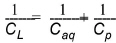
Wetted Perimeter - MIKE SHE uses the inner wetted perimeter if the flow is from MIKE URBAN to MIKE SHE. Whereas, it uses the outer wetted perimeter if the flow is from MIKE SHE to MIKE URBAN. The wetted perimeters are calculated by MIKE URBAN.
MIKE SHE Overland flow to MIKE URBAN LINKS
If a MIKE URBAN link is defined as link type CRS or Natural Channel and has a cross section which is "open", then MIKE SHE can exchange overland flow with it in both directions. In this case, the exchange coefficient in Equation (32.1) is defined as
(32.7) 
where CL is the conductance and L is the length of the MIKE URBAN pipe (link) in the MIKE SHE cell.
If the exponent Equation (32.1) is 1.0, then this is a simple drain formulation and the conductance is per length with units of [m/s]. If the exponent is 1.5, then this is a weir formulation and the units of the conductance term are [m1/2/s].
MIKE SHE Overland flow to MIKE URBAN Manholes
If the MIKE URBAN manholes are not sealed, then MIKE SHE can discharge overland flow into the MIKE URBAN manholes. In this case, the exchange coefficient in Equation (32.1) is defined as
(32.8) 
where CL is the conductance.
If the exponent Equation (32.1) is 1.0, then this is a simple drain formulation and the conductance, CL, is per length with units of [m/s]. If the exponent is 1.5, then this is a weir formulation and the units of the conductance term are [m1/2/s].
MIKE SHE SZ drain flow to MIKE URBAN Manholes
If drain flow is specified in MIKE SHE, then the drainage can be discharged to a MIKE URBAN manhole. The flow in the drain is calculated by MIKE SHE based on the groundwater height above the drain level. In MIKE SHE the distributed drainage option must be chosen (see Drainage (V1 p. 325)) and the cells that drain to a manhole must have an option value of 4 (see Option Distribution (V1 p. 331)). The references between the MIKE SHE drain codes and the MIKE URBAN manholes are defined in the MsheMouse.pfs file (see Creating a MsheMouse.pfs file (V1 p. 652)).
MIKE SHE Ponded Drainage to MIKE URBAN Manholes
If the Ponded Drainage option is used in MIKE SHE, then the ponded water can be discharged to a MIKE URBAN manhole. MIKE SHE’s ponded drainage module uses a user-defined source-destination reference system.
MIKE URBAN Outlets to MIKE SHE
MIKE URBAN outlets cannot directly discharge to MIKE SHE’s overland flow. To work around this, you can add a dummy manhole to your MIKE URBAN pipe and then couple the pipe to the outlet via a small diameter dummy pipe (See Figure 32.2). This will force most of the water out of the manhole and into MIKE SHE’s overland flow. Downside of this method, is that the head loss at the outlet is over estimated, because the discharge velocity is zero at a manhole.
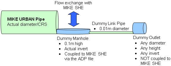
Figure 32.2 Work around for discharging MIKE URBAN outlets to MIKE SHE
![]()