Multi-cell Overland Flow Method
The resolution of available topography data is often greater than the practical discretization of the overland flow model. This means that important topographic detail is often neglected in the overland flow model. The multi-cell overland flow method attempts to mitigate this discrepancy.
In the Multi-cell overland flow method, high resolution topography data is used to modify the flow area used in the St Venant equation and the courant criteria. The method utilizes two grids - a fine-scale topography grid and a coarser scale overland flow calculation grid. However, both grids are calculated from the same reference data - that is the detailed topography digital elevation model.
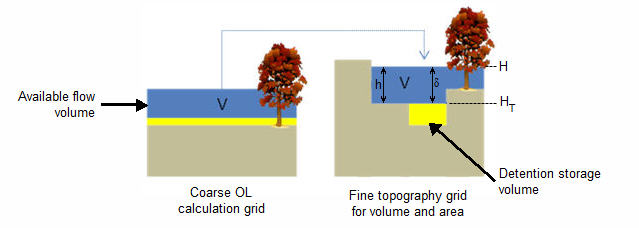
In the Multi-cell method, the principle assumption is that the volume of water in the fine grid and the coarse grid is the same. Thus, given a volume of water, a depth and flooded area can be calculated for both the fine grid and the coarse grid. See Figure 24.7.
In the case of detention storage, the volume of detention storage is calculated based on the user specified depth and OL cell area.
Figure 24.7 The constant volume from the coarse grid is transfered to the fine scale grid.
According to the Gauckler-Manning-Strickler formula, overland sheet flow can be expressed as
(24.27) 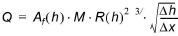
Where Af is the flow area, M is the Manning number, h is the water depth, Dx is the grid size and R is the hydraulic radius which, for practical reasons, is replaced by the resistance radius in the multi-cell method. Thus,
(24.28) 
which expands to
For any cross-section of flow, the resistance radius is calculated by
(24.30) 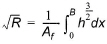
where again h is the local water depth and B is the total width of the cross-section.
Thus, in a cross-section divided into n equal sub-grids,
where hi is the local water depth in each sub-grid. Since, Af is equal to
The resistance radius can be simplified to
However, since parts of the sub-section may be dry, or the entire depth may not be available for flow because of detention storage, the actual resistance radius in the cross section is
where
(24.35) 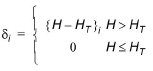
in which H is the water level in the refined cross-section and HT is the maximum of the topography and level of detention storage in the current sub-grid.
Now, we need to apply the above formulation to a 2D coarse grid cell. In this case, the flow area and resistance radius is an average of the values along each row and column in the cell.
Thus, from Equation (24.32), the flow area for the x and y flow directions for each coarse grid cell is
(24.36) 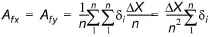
and from Equation (24.34), the resistance radius for the x and y flow directions for each coarse grid cell is
(24.37) 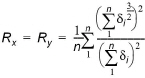
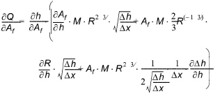
Finally, the courant criteria also includes the flow area. Thus, from Equation
(24.38) 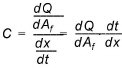
which implies that the maximum allowed time step, Dt,when using the multi-grid method is
(24.39) 
where Dx is the coarse overland flow grid size, the denominator is defined by Equation (24.29), and C is the user-specified courant criteria.
Implementation and Limitations
When using the multi-cell overland flow method, each overland flow cell is divided into an integer number of sub-grid cells (e.g. 4, 9, 16, 25, etc). The elevation of the coarse grid nodes and the fine grid nodes are calculated based on the input data and the selected interpolation method. However, the coarse grid elevation is adjusted such that it equals the average of the fine grid nodal elevations. This provides consistency between the coarse grid and fine grid elevations and storage volumes. Therefore, there may be slight differences between the cell topography elevations if the multi-cell method is turned on or off. This could affect your model inputs and results that depend on the topography. For example, if you initial water table is defined as a depth to the water table from the topography.
Overland flow exchange with MIKE Hydro River does not consider the multi-cell method. That is, flow into and out of the River Links is controlled by the water level calculated from the elevation defined in the coarse grid cell. Likewise the flow area for exchange with MIKE Hydro River is calculated as the coarse water depth times the overall grid size. Also, the elevation used when calculating flood inundation with flood codes only considers the average cell depth of the coarse grid.
However, if you choose to modify the topography based on a bathymetry file, or the MIKE Hydro River cross-sections, then this information will be used when calculating the multi-cell elevations.
Evaporation is adjusted for the area of ponded water in the coarse grid cell. That is, evaporation from ponded water is reduced by a ponded area fraction, calculated by dividing the area of ponding in the fine grid cell by the total cell area.
Infiltration from ponded water to the underlying UZ column or exchange between SZ and OL does not consider the multi-cell elevations. In both of these cases, only the average coarse grid elevation is used.
![]()