OL Drainage Reference System
The OL Drainage function requires a reference system for linking the drainage to a recipient node or cell. The recipient can be a MIKE Hydro River node, another OL grid cell, or a model boundary.
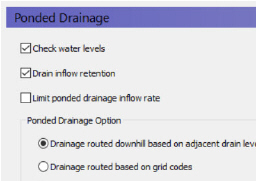
There are four different options for setting up the drainage source-recipient reference system
.
Drainage routed downhill based on adjacent drain levels
The reference system is created automatically by the pre-processor using the slope of the drains calculated from the drainage levels in each cell.
Thus, the pre-processor calculates the drainage source-recipient reference system by
1. looking at each cell in turn and then
2. looking for the neighbouring cell with the lowest drain level.
3. If this cell is an outer boundary cell or contains a river link, the search stops.
4. If this cell does not contain a boundary or river link, then the search is repeated with the next downstream neighbour until either a local minimum is found or a boundary cell or river link is found.
The result of the above search from each cell is used to build the source-recipient reference system.
If local depressions in the drainage levels exist, the OL nodes in these depressions may become the recipients for a number of drain flow producing nodes. This often results in the creation of a small lake at such local depressions.
The drain-slope based reference system has been used in MIKE SHE for many years in SZ and works well in most situations. However, when MIKE SHE is applied where there is very little surface relief, it is often difficult to establish a suitable reference system based on the surface topography/drain slopes. In flat areas, this may generate many undesired local depressions, which may receive drainage water from a large area, thus generating lakes in places where there should not be a lake.
If the drain level is perfectly flat, drainage is turned off. In other words, if the drain-slope method cannot find a downhill neighbour because all the neighbours have the same elevation as the cell, the drain slope method assumes that the cell is a local depression. However, the depression has no sources of drainage except itself. Thus, the drainage function is effectively turned off.

Tip: MIKE SHE considers a grid point to be a local depression even if the drainage level in the four surrounding model grids is only 1 mm higher. The only way to avoid such problems is to create a drain level map that does not contain artificial local depressions. For large models this may be difficult and time consuming. In this case, one of the other drainage options may be better.

Remember, the drainage is routed to a destination. It does not physically flow downhill. The drain levels are only used to build the drainage source-recipient reference system, and to calculate the amount of drainage.
Drainage routing based on grid codes
This method is often used when the topography is very flat, which can result in artificial depressions, or when the drainage system is very well defined, such as in urban applications.
In this method, the drainage levels and the time constants are defined as in the previous method and the amount of drainage is calculated based on the drain levels and the time constant.
If the drainage routing is specified by Drain Codes, a grid code map is required that is used to restrict the search area for the source-recipient reference system. In this case, the pre-processer calculates the reference system within each grid code zone, such that all drainage generated within one zone is routed to recipient nodes with the same drain code value.
When building the reference system, the pre-processor looks at each cell and then
1. looks for the nearest cell with a river link with the same grid code value,
2. if there is no cells with river links, then it looks for the nearest outer boundary cell with the same grid code,
3. if there are no cells with outer boundary conditions, then it looks for the cell with the same grid code value that has the lowest drain level. In this case, the reference system is calculated as if it was based on Drain Levels (see previous section).
The result of the above search for each cell is used to build the source-recipient reference system.
The above search algorithm is valid for all positive Drain Code values. However, all cells where
· Drain Code = 0 - will not produce any drain flow and will not receive any drain flow, and
· Drain Code < 0 (negative) - will not drain to river links, but will start at Step 2 above and only drain to either a outer boundary or the lowest drain level.

Tip: One method that can be used is to specify one Drain Code value for the entire model area (e.g. Drain Code = 1). Thus, all nodes can drain and any drain flow is routed to the nearest river link. If there are no rivers, the drain flow will be routed to the nearest boundary. If you want to route all drain flow to the boundaries instead of the rivers, a negative drain code can be specified for the entire area (e.g. Drain Code = -1).
Choosing this method, adds the Option Distribution item to the data tree. With the Option Distribution, you can specify an integer grid code distribution that can be used to specify different drainage options in different areas of your model.
· Code = 1 - In grid cells with a value of 1, the drainage reference system is calculated based on the Drain Levels.
· Code =2 - In grid cells with a value of 2, the drainage reference system is calculated based the Drain Codes.
· Code = 3 - Drainage in grid cells with a value of 3 is routed to a specified MIKE Hydro River branch and chainage. At the moment, this options requires the use of Extra Parameters (V1 p. 347) and is described in OL Drainage to Specified MIKE Hydro River H-points (V1 p. 747).
· Code = 4 - Drainage in grid cells with a value of 4 is routed to a specified MIKE URBAN man hole. At the moment, this options requires the use of Extra Parameters (V1 p. 347) and is described in the section Using MIKE SHE with MIKE URBAN (V1 p. 647).
Drain flow not routed, by removed from model
The fourth option simply removes the water from the model. This is equivalent to routing all the drainage to a boundary.
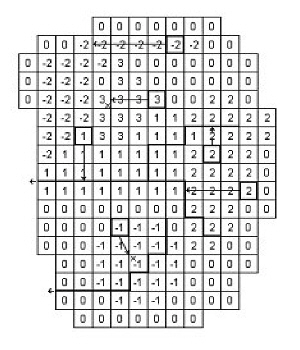
· The grid cells with Drain Code 3 drain to a local depression since no boundary or river link is found adjacent to a grid with the same drain code.
· The grid cells with Drain Code 1 or 2 drain to nearest river link located adjacent to a grid with the same drain code.
· The grid cells with drain code 0 do not contain drains and thus no drainage is produced.
· The grid cells with Drain Code -1 drains to local depression since no boundary is found adjacent to a grid with the same drain code.
· The grid cells with Drain Code -2 drains to nearest boundary grid with the same drain code.
![]()