The upper boundary of the top layer is always either the infiltration/exfiltration boundary, which in MIKE SHE is calculated by the unsaturated zone component or a specified fraction of the precipitation if the unsaturated zone component is excluded from the simulation.
The lower boundary of the bottom layer is always considered as impermeable.
In MIKE SHE, the rest of the boundary conditions can be divided into two types: Internal and Outer. A boundary condition in one of the cells on the edge of the model domiain is “outer boundary”. All other boundary conditions inside the domain are call “internal boundaries”.
Groundwater Drainage
Saturated zone drainage is a special boundary condition in MIKE SHE used to defined natural and artificial drainage systems that cannot be defined in MIKE Hydro River. It can also be used to simulate simple overland flow, if the overland flow system can be conceptualized as a shallow drainage network connected to the groundwater table - for example, on a flood plain.
Saturated zone drainage is removed from the layer of the Saturated Zone model containing the drain level. Water that is removed from the saturated zone by drains is routed to local surface water bodies, local topographic depressions, or out of the model.
When water is removed from a drain, it is immediately moved to the recipient. In other words, the drain module assumes that the time step is longer than the time required for the drainage water to move to the recipient. This is the same as a “full pipe”. That is, water added to the end of a full pipe of water causes an equal amount of water to immediately flow out the opposite end - regardless of the length of the pipe.
Drain flow is simulated using an simple linear reservoir formula. Each cell requires a drain level and a time constant (leakage factor). Both drain levels and time constants can be spatially defined. A typical drainage level is 1m below the ground surface and a typical time constant is between 1e-6 and 1 e-7 1/s.
Drainage reference system
MIKE SHE also requires a reference system for linking the drainage to a recipient node or cell. The recipient can be a MIKE Hydro River node, another SZ grid cell, or a model boundary.
There are four different options for setting up the drainage source-recipient reference system
Drainage routed downhill based on adjacent drain levels
This option was originally the only option in MIKE SHE. The reference system is created automatically by the pre-processor using the slope of the drains calculated from the drainage levels in each cell.
Thus, the pre-processor calculates the drainage source-recipient reference system by
1. looking at each cell in turn and then
2. looking for the neighbouring cell with the lowest drain level.
3. If this cell is an outer boundary cell or contains a river link, the search stops.
4. If this cell does not contain a boundary or river link, then the search is repeated with the next downstream neighbour until either a local minimum is found or a boundary cell or river link is found.
The result of the above search from each cell is used to build the source-recipient reference system.
If local depressions in the drainage levels exist, the SZ nodes in these depressions may become the recipients for a number of drain flow producing nodes. This often results in the creation of a small lake at such local depressions. If overland flow is simulated, then the ponded drainage water will become part of the local overland flow system.
Drain levels above the topography are not allowed. In this case a warning will be written to the PP_Print.log and the drain level will be automatically adjusted to a value just below the topography.
The drain level method is not allowed when using Time varying SZ drainage parameters (V1 p. 761) because the source-recipient reference system is only calculated once at the beginning of the simulation.
The drain-slope based reference system has been used in MIKE SHE for many years and works well in most situations. However, when MIKE SHE is applied where there is very little surface topographic relief, it is often difficult to establish a suitable reference system based on the surface topography/drain slopes. For example, often it is assumed that the drains are located 50 to 100 cm below the terrain. In flat areas, this may generate many undesired local depressions, which may receive drainage water from a large area, thus generating lakes in places where there should not be a lake.
If the drain level is perfectly flat, drainage is turned off. In other words, if the drain-slope method cannot find a downhill neighbour because all the neighbours have the same elevation as the cell, the drain slope method assumes that the cell is a local depression. However, the depression has no sources of drainage except itself. Thus, the drainage function is effectively turned off.

Tip: MIKE SHE considers a grid point to be a local depression even if the drainage level in the four surrounding model grids is only 1 mm higher. The only way to avoid such problems is to create a drain level map that does not contain “wrong” local depressions. For large models this may be difficult and time consuming. In this case, one of the other drainage options may be better.

Remember, the drainage is routed to a destination. It does not phyisically flow downhill. The drain levels are only used to build the drainage source-recipient reference system, and to calculate the amount of drainage.
Drainage routing based on grid codes
This method is often used when the topography is very flat, which can result in artificial depressions, or when the drainage system is very well defined, such as in agricultural applications.
In this method, the drainage levels and the time constants are defined as in the previous method and the amount of drainage is calculated based on the drain levels and the time constant.
If the drainage routing is specified by Drain Codes, a grid code map is required that is used to restrict the search area for the source-recipient reference system. In this case, the pre-processer calculates the reference system within each grid code zone, such that all drainage generated within one zone is routed to recipient nodes with the same drain code value.
When building the reference system, the pre-processor looks at each cell and then
1. looks for the nearest cell with a river link with the same grid code value,
2. if there is no cells with river links, then it looks for the nearest outer boundary cell with the same grid code,
3. if there are no cells with outer boundary conditions, then it looks for the cell with the same grid code value that has the lowest drain level. In this case, the reference system is calculated as if it was based on Drain Levels (see previous section).
The result of the above search for each cell is used to build the source-recipient reference system.
The above search algorithm is valid for all positive Drain Code values. However, all cells where
Drain Code = 0 - will not produce any drain flow and will not receive any drain flow, and
Drain Code < 0 (negative) - will not drain to river links, but will start at Step 2 above and only drain to either a outer boundary or the lowest drain level.

Tip: One method that is often used is to specify only one Drain Code value for the entire model area (e.g. Drain Code = 1). Thus, all nodes can drain and any drain flow is routed to the nearest river link. If there are no rivers, the drain flow will be routed to the nearest boundary. If you want to route all drain flow to the boundaries instead of the rivers, a negative drain code can be specified for the entire area (e.g. Drain Code = -1).
Choosing this method, adds the Option Distribution item to the data tree. With the Option Distribution, you can specify an integer grid code distribution that can be used to specify different drainage options in different areas of your model.
Code = 1 - In grid cells with a value of 1, the drainage reference system is calculated based on the Drain Levels.
Code =2 - In grid cells with a value of 2, the drainage reference system is calculated based the Drain Codes.
Code = 3 - Drainage in grid cells with a value of 3 is routed to a specified MIKE Hydro River branch and chainage. At the moment, this options requires the use of Extra Parameters (V1 p. 347) and is described in SZ Drainage to Specified MIKE Hydro River H-points (V1 p. 758).
Code = 4 - Drainage in grid cells with a value of 4 is routed to a specified MOUSE man hole. At the moment, this options requires the use of Extra Parameters (V1 p. 347) and is described in the section Using MIKE SHE with MIKE URBAN (V1 p. 647).
Drain flow not routed, by removed from model
The fourth option is simply a head dependent boundary that removes the drainage water from the model. This method does not involve routing and is exactly the same as the MODFLOW Drain boundary.
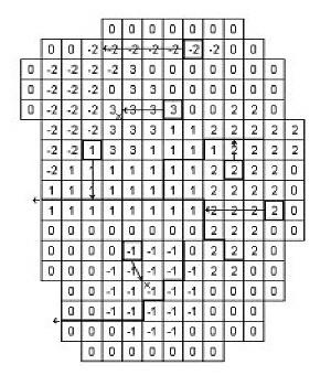
· The grid cells with Drain Code 3 drain to a local depression since no boundary or river link is found adjacent to a grid with the same drain code.
· The grid cells with Drain Code 1 or 2 drain to nearest river link located adjacent to a grid with the same drain code.
· The grid cells with drain code 0 do not contain drains and thus no drainage is produced.
· The grid cells with Drain Code -1 drains to local depression since no boundary is found adjacent to a grid with the same drain code.
· The grid cells with Drain Code -2 drains to nearest boundary grid with the same drain code.
The Pre-processed Drainage Reference System
During the preprocessing, each active drain cell is mapped to a recipient cell. Then, whenever drainage is generated in a cell, the drain water will always be moved to the same recipient cell. The drainage source-recipient reference system is displayed in the following two grids in the Pre-processed tab, under the Saturated Zone:
· Drain Codes - The value in the pre-processed Drain Codes map reflects the Option Distribution specified. For example, those cells with an Option Distribution equal to 1 (Drainage routed based on Drain Levels) will have a pre-processed Drain Code equal to 0, because the Drain Codes are not being used for those cells.
· Drainage to local depressions and boundary - This grid displays all the cells that drain to local depressions or to the outer boundaries. All drainage from cells with the same negative value are drained to the cell with the corresponding positive code. If there is no corresponding positive code, then that cell drains to the outer boundary, and the water is simply removed from the model. Cells with a delete value either do not generate drainage, or they drain to a river link.
· Drainage to river - This grid displays the river link number that the cell drains to. Adjacent to the river links, the cells are labeled with negative numbers to facilitate the interpretation of flow from cells to river links. Thus, in principle, all drainage from cells with the same positive code are drained to the cell with the corresponding negative code.
However, this is slightly too simple because the cells actually drain directly to the river links. In complex river systems, when the river branches are close together, you can easily have cells connected to multiple branches on different sides. In this case, the river link numbers along the river may not reflect the drainage-river link reference used in the model.
If you want to see the actual river links used in all cells, you can use the Extra Parameter, Canyon exchange option for deep narrow channels (V1 p. 764), to generate a table of all the river link-cell references in the PP_Print.log file.
Cells with a value of zero either do not generate drainage, or they drain to a the outer boundary or a local depression.
![]()