
Most dambreak setups consist of a single or several channels, a reservoir, the dam structure and perhaps auxiliary dam structures such as spillways, bottom outlets etc. Further downstream the river may be crossed by bridges, culverts etc. It is important to describe the river setup accurately in order to obtain reasonable results. There is no limit to the number of dambreak structures in a MIKE HYDRO River model.
Due to the highly unsteady nature of dambreak flood propagation, it is advisable that the river topography be described as accurately as possible through the use of as many cross-sections as necessary, particularly where the cross-sections are changing rapidly.
Another consideration is that the cross-sections themselves should extend as far as the highest modelled water level, which will normally be in excess of the highest recorded flood level. If the modelled water level exceeds the highest level in the cross-section for a particular location, MIKE HYDRO River will extrapolate the PROCESSED data using an assumption of ‘vertical walls’ (keeping the top-width of cross sections when calculating hydrodynamic parameters above top-level of sections).
Note: When performing dambreak simulations, initial conditions should be set up with care, in order to obtain relevant results. Indeed, the discharge through the breach may highly depend on the downstream water level, therefore if the breach fails early in the simulation, the results may be influenced by the initial condition. It is advised to make sure that water levels and discharge throughout the domain, just before the failure, correctly represent the expected conditions. Additionally, initial conditions may create oscillations at the beginning of the simulation, which can unexpectedly trigger the failure of the dam in case the failure moment is controlled by the upstream water level. A hotstart initial condition may be used to achieve this.
General
Breach details
Dambreak reservoir description and auxiliary structures
Spillways and other structures
The General tab is used for specifying the main properties of the dam and its break. The page consists of a number of dialogue boxes whose functionality is described below.
Location
ID. String identification of the structure. It is used to identify the structure if there are multiple structures at the same location. It is recommended always to give the structure an ID.
Branch name. Name of the river branch in which the dambreak is located.
Chainage. Chainage at which the dambreak is located.
Type: The location type may be Regular, Side structure or Side structure with storage. See section Structure types definition (p. 114) for details.
Breach formula
The calculation of the dam break may be carried out using two different formulas. These will also affect the available options for geometry and failure mode. The breach formula available are:
· Energy equation.
· NWS DAMBRK equation (from US National Weather Service).
Failure mode
The development of the breach can take place in different ways. The failure mode of the structure is affected by the chosen breach formula.
When the energy equation is used to compute the dam break, the failure mode choices are:
· Time dependent. The development of the dam breach is specified by the user in terms of breach level, width and slope as functions of time (these are specified in the Breach details tab).
· Erosion based. The breach development is calculated by use of a sediment transport formula for which the parameters are specified in the Breach details tab.
If the NWS DAMBRK equation is selected the options are:
· Breach failure. The dam break initiates as a breach of the crest.
· Piping failure. The dam break initiates as a piping failure, the shape of the pipe being trapezoidal.
Geometry
Crest level before failure. The initial crest level of the dam before failure.
Crest length before failure. The initial crest length (perpendicular to the flow) of the structure before failure.
Additionally, when the Energy equation is selected as breach formula, in combination with the Time dependent failure mode, the following must be specified:
Apply limiting section. If you select this option the development of the breach is limited (e.g. due to solid rock below the dam), otherwise it will be unlimited. The shape of the limitation should be specified in the
Cross section dialogue. When this option is selected, the following parameters should also be specified:
· Branch name. Name of the river branch in which the limiting section in the cross section dialogue is located.
· Topo ID. Topo ID in which the limiting section in the cross section dialogue is located.
· Chainage. Chainage of the limiting section in the cross section dialogue.
· S-coordinate of breach’s centre. The S-coordinate of the limiting section which is aligned with the breach centreline.
When the Energy equation is selected as breach formula, in combination with the Erosion based failure mode, a limiting breach geometry must be specified using the following parameters:
· Minimum bottom level. Minimum bottom level of the trapezoidal shape describing the breach.
· Maximum bottom width. Maximum bottom width of the trapezoidal shape describing the breach.
· Maximum breach slope. Maximum transversal slope (horizontal: vertical) on the sides of the trapezoidal shape describing the breach.

Note: The discharge through the dam is continuously computed through two separate structures, respectively describing the crest of the dam and the breach. After the failure, the width of the crest varies in time, and is equal to the Crest level before failure minus the instantaneous breach width. For this reason, the breach width cannot become longer than the Crest level before failure.
Failure moment
The moment at which the dam failure commences can be defined in the following ways:
· Hours after start. The failure is specified to take place at a specified number of hours after the start of the simulation.
· Date and time. The failure time is specified as a specific date and time.
· Reservoir water level. The failure is specified to take place when the water level in the reservoir (assumed to be the grid point immediately upstream of the dam) exceeds the specified level.
· Control rule. This option allows to use a user-defined rule to define the failure moment. This rule is defined in the Control rules menu, and may depend on e.g. instantaneous results or external data.
Head Loss Factors
The factors determining the energy loss occurring for flow over/through the hydraulic structure. These input parameters are only required for the energy loss method and must be specified for both Positive and Negative flow.
Inflow, Outflow and Free overflow. Energy loss coefficient for the specific types of flow.
Flow blockage
Apply flow factor.
When this option is active, the discharge computed through the dambreak is multiplied by a flow factor. This factor's value is specified in the Flow factor field. The factor is a dimensionless factor, and a value of 1 means that no change is applied to the computed discharge. A value lower than 1 can typically be used to describe the reduction of the flow through the structure due to obstacles, like debris, restricting the flow area in the structure.
This tab contains different parameters depending on the choice made for the breach formula and failure mode.
For the Erosion based failure mode, which can be selected when the Energy equation is used as breach formula, the following dialogues and parameters are available in the Breach details tab.
For this case, the vertical development of the breach is calculated using the Engelund-Hansen sediment transport formula. Breach width is determined from the product of breach depth and the side erosion index specified by the user.
Dam geometry
Up stream slope. Longitudinal slope (horizontal:vertical) of the upstream face of the dam structure.
Down stream slope. Longitudinal slope (horizontal:vertical) of the downstream face of the of the dam structure.
Top width. The top width of the dam crest, in the longitudinal direction.
Material properties
Grain diameter. Representative grain diameter of the dam core material.
Specific gravity. Relative density of the dam core material. Usually ranging between 2.5 - 2.7.
Porosity. Porosity of the dam core material. 0.3 - 0.5.
Critical shear stress. Critical shear stress of dam core material used for sediment transport estimation (Shields criteria). Usually ranging between 0.03 - 0.06.
Side erosion index. Multiplication factor used to calculate breach width erosion rates from breach depth predictions.
Initial failure
Type of initial failure. The failure of the dam can initially take place in two ways:
· Breach failure: a breach starting at the crest of the dam
· Piping failure: a piping failure through the dam.
For the Breach failure type, the additional parameters below must be specified:
· Initial level after failure. The bottom level of the trapezoidal breach at the first time step after the failure moment.
· Initial width after failure. The bottom width of the trapezoidal breach at the first time step after the failure moment.
For the Piping failure type, the additional parameters below must be specified:
· Starting level. The pipe’s centre level at which piping failure begins to occur.
· Initial diameter. The diameter of the piping breach at the first time step after the failure moment.
· Roughness. Pipe roughness used to calculate the Darcy friction factor.
· Collapse ratio (D/y). When the ratio between the diameter of the pipe (D) and the distance from the top of the dam to the top of the pipe (y) is larger than the collapse ratio, the pipe collapses. After it has collapsed, the breach is modelled using a trapezoidal breach.
· Volume loss ratio. When the dam collapses some of the material may be carried out without depositing on the bed of the breach. The volume loss ratio is the fraction of the material to be washed out immediately after collapse. It ranges in the interval 0 – 1.
· Calibration coefficient. Calibration multiplication factor used to adjust the calculated change in pipe radius.
In all the other cases, i.e. when the Energy equation is used in the breach formula and the failure mode is Time dependent, as well as when the NWS DAMBRK equation is selected as breach formula, only the parameters of the temporal description of the dam geometry must be specified.
Temporal description of geometry
When using the NWS DAMBRK equation, or the Energy equation with the Time dependent failure mode, the breach geometry is defined with the following parameters:
· Breach bottom level. The bottom level of the trapezoidal shape of the breach.
· Breach bottom width. The bottom width of the trapezoidal shape of the breach.
· Transversal slope. The transversal slope (horizontal:vertical) on both sides of the breach.
· Pipe top level. Upper level of the pipe. This option is available only if NWS piping failure is selected.
All these geometry features can be defined either as constant values or as time varying ones. For the latter it is necessary to select a dfs0 file, and select the appropriate item if the file contains more than one item.
Dambreak reservoir description and auxiliary structures
To obtain an accurate description of the Dam reservoir storage characteristics, the reservoir can be modelled either as a single h-point in the model or as a branch with a number of cross sections correctly defining the topography and hence, volume characteristics along the reservoir.
In case the reservoir is represented by only one h-point, this will also corresponds to the upstream boundary of the model where inflow hydrographs are specified.
The description of the reservoir storage in this case is defined in the processed data of the cross section in this point. The columns relevant to consider for defining a level storage relation of the reservoir are water level and the additional flooded area columns.
Thereby, the surface storage area of the dam is described as a function of the water level. The lowest water level should be somewhere below the final breach elevation of the dam, and should be associated with some finite flooded area. (This first value, hence, describes a type of 'slot' in the reservoir).
The cross-sectional area is set to a large finite value. It is only used when calculating the inflow headloss into the breach.
It may be practical to locate the dambreak structure on a separate branch containing only three calculation points, as shown in Figure 6.32.
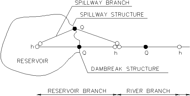
Figure 6.32 Example of Dambreak simulation setup schematisation
Spillways and other structures
If a spillway is added to the dam itself, it could be described as a separate branch, see Figure 6.32.
At the node where the two branches meet, the surface flooded area is taken as the sum of the individual flooded areas specified at each h-point.
Hence, if the reservoir storage has already been described in the reservoir h-point, the spillway h-point should contain no additional surface areas. In this case both the width and the additional flooded areas should be set to zero. The cross-sectional area, hydraulic radii, etc. can be given as for the reservoir branch.
It is not a requirement that a separate branch for the spillway structure is defined. The dambreak and the spill way structure can be located in the same grid point, i.e. as a composite structure. The advantage of having two separate branches is that the discharge through the spillway and the dambreak structure is given as two separate time series in the result file.
![]()