The General tab includes that majority of definitions for structures. The following parameters can be specified.
Location
ID.
String identification of the weir. ID will be used in structure results and hence makes it easier to identify a specific structure if setup contains many structures, or if multiple structures are defined at the same location.
Branch name.
The Branch name is automatically registered where the weir is located.
Chainage.
Chainage at which the weir is located.
Type.
The location type may be defined as Regular, Side Structure or Side Structure with Reservoir. See Structure types definition (p. 114) for details.
Graphics
Horizontal offset from marker 2.
The horizontal position of the weir within the cross section can be defined. By default the centre of the weir is positioned at marker 2. Note that the position is used only to plot/display the weir and has no impact on the simulation.
Geometry
Here, the geometry of the weir is defined. The exact contents of the dialogue window depends on the type of weir.
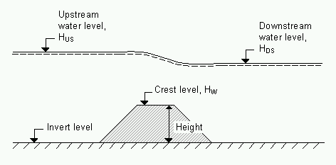
Figure 6.20 Definition sketch for Weir formula

Note: Since a weir is defined as a structure causing a contraction loss and subsequently an expansion loss, the geometry of the weir must be such that the cross sectional area at the weir is less than the cross sectional area at both the upstream and the downstream cross section for all water levels.
Broad Crested weirs
Type.
Broad Crested weirs have two different ways for defining the weir geometry:
· Level-Width: The weir geometry is specified as levels (relative to the datum) and corresponding flow widths.
Datum: Offset which is added to the level column in the level/width table.
Level/Width table: This table includes user defined levels and corresponding flow widths. Click on the Append button to add rows to the table. Note that values in the ‘Level’ column must be increasing.
· Cross Section DB: The weir geometry is specified in the cross section editor. Select the branch name, TopoID and chainage of the cross section, which describes the structure’s geometry.
Villemonte formula
Width.
Width of the flow.
Height.
Weir height. See Figure 6.20.
Invert Level.
Bottom datum level. See Figure 6.20.
Honma formula
Width.
Width of the flow.
Crest level.
Weir level. See Figure 6.20.
Extended Honma formula
Width.
Width of the flow.
Height.
Weir height. See Figure 6.20.
Crest level.
Weir level. See Figure 6.20.
Attributes
Weir type.
The Weir type defines the type of Weir formulation used to calculate the flow dynamics over the structure:
· Broad Crested:
For Broad Crested weirs a hydrostatic pressure condition is assumed and the Q/h relationship is calculated automatically.
· Villemonte Formula:
A standard weir expression reduced according to the Villemonte formula is applied. See the MIKE 1D Reference Manual.
· Honma Formula:
The Honma weir expression. See the MIKE 1D Reference Manual.
· Extended Honma Formula:
An extended version of the Honma weir formula is applied. See the MIKE 1D Reference Manual.
Valve.
Valves may be included to control the direction of the overflow.
· None:
No valve regulation applies.
· Only Positive Flow:
Only positive flow is allowed, i.e. whenever the water level downstream is higher than upstream the flow through the structure will be zero.
· Only Negative Flow:
Only negative flow is allowed, i.e. whenever the water level upstream is higher than downstream the flow through the structure will be zero.
· No Flow:
The flow through structures will always be zero, regardless of upstream and downstream water levels.
Flow blockage
Apply flow factor
When this option is active, the discharge computed through the weir is multiplied by a flow factor. This factor's value is specified in the Flow factor field. The factor is a dimensionless factor, and a value of 1 means that no change is applied to the computed discharge. A value lower than 1 can typically be used to describe the reduction of the flow through the structure due to obstacles, like debris, restricting the flow area in the structure.
Head loss
The factors determining the energy loss occurring for flow through hydraulic structures (only active for broad crested weirs). Head loss factors can be defined with different values depending on the flow direction across the weir (positive or negative flow direction).
Weir formula parameters
Here the Weir formula parameters are specified. The contents of the dialogue depends on the type of weir (and is not relevant for Broad Crested weirs).
Villemonte formula
The Villemonte formula reads:
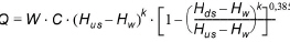
Where Q is discharge through the structure, W is width, C is weir coefficient, k is the weir exponential coefficient, Hus is upstream water level, Hds is downstream water level and Hw is weir level.
Weir coefficient.
Weir coefficient is the multiplication coefficient ‘C’ in the weir formula.
Weir exponential coefficient.
Weir exponent coefficient is the exponential coefficient ‘k’ in the weir formula.
Honma formula
The Honma formula reads:
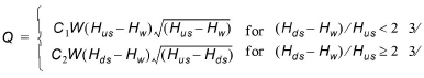
Where Q is the discharge through structure, W is the width, C1 is the first weir coefficient,
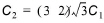
is the second weir coefficient, Hus is the upstream water level, Hds is the downstream water level and Hw is weir level
Weir coefficient.
The Weir coefficient is the multiplication coefficient ‘C1’ of the Honma weir formula.
Extended Honma formula
The Extended Honma formula calculates the flow in three flow regimes: 1) perfect flow, 2) imperfect flow, and 3) submerged overflow. The equations reads:
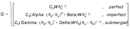
where
W is weir width
H is weir height above cross section invert
hd is the upstream water level above the crest
hu is the down stream water level above the crest
Perfect overflow parameters
(hd/hu)i is the depth ratio limit between perfect and imperfect flow regime.
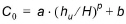
Parameters a, b and p are used to calculate the weir coefficient C0.
Imperfect overflow parameters
Parameters Alpha, Beta and q are used in imperfect overflow calculation
Submerged overflow parameters
(hd/hu)s is the depth ratio limit between imperfect and submerged flow regime.
Parameters; Gamma, Delta and r used in Submerged overflow calculation

Note: It is not checked if there is a continuous transition from one flow regime to the next. This has to be ensured by the user through proper selection of the parameters.
For broad crested weirs an additional tab is shown for flow conditions. Free overflow Q/h relations are calculated automatically by clicking ‘Calculate Q/h relations’ once the no. of Q/h relations have been specified.
The results are shown in the Q/h-relations table and includes:
· Q: Structure discharge
· H-Pos: Level upstream in case of positive flow
· H-Neg: Level downstream in case of negative flow
· H-Weir: Level at structure
· Width: Structure width for actual structure level
· Area: Structure area for actual structure level
To compute the Q/h relations, the nearest upstream and downstream cross sections are used. The cross sections must be located within a distance which is smaller than the user-defined maximum grid-spacing (‘Maximum dx’) for the branch in question. The Q/h relations cannot be calculated unless cross sections are defined.

Note that Q/h relations must be re-calculated if any changes are made to the weir and/or up/down-stream cross sections. This is done by either pressing the button ‘Calculate Q/h relations’ for an individual structure or by selecting ‘Recalculate flow conditions...’ in the ‘Run’ drop- down menu in the MIKE Zero menu bar for recalculating all structures.
Allow for recalculation. Q/h relations can either be calculated automatically or entered/edited manually. If the Q/h relations have been modified manually it is possible to lock the relations by unchecking ‘Allow for recalculation’. This will ensure that Q/h relations for this structure are not recalculated through the menu ‘Recalculate flow conditions...’.
![]()