Creating a Rectangular Grid Workflow Example
1. Load desired input topographical layers for 2D grid interpolation into the MIKE+ project.
2. On the 2D Domain editor, choose a ‘Rectangular grid’ domain type and ‘Domain file created from MIKE+ definition’ as source. Specify the file name and path for the domain file to be created.
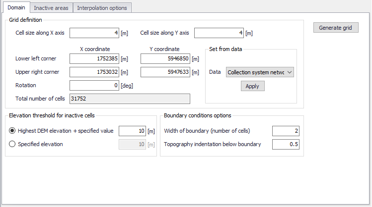
3. Configure grid domain parameters. Specify grid cell size along the x and y directions, and define the domain grid extent.
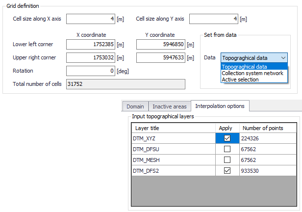
You may choose to set the extent from Topographical data. If so, ensure that the appropriate topographical data layer is activated in the ‘Interpolation Options’ tab.
You may also chose to define the grid extent by drawing it on the map. In the 2D overland ribbon, select the 'Grid definition' layer to draw a rectangle defining this extent. While editing this rectangle on the map, it is possible to resize and rotate it.
4. Customize other parameter values on the Domain tab, such as those under the ‘Elevation threshold for inactive cells’ and ‘Boundary condition options’ sections, if so desired. More details on these options are described in Chapter 3.1.2.
5. Click on the ‘Generate grid’ button on the Domain tab page.
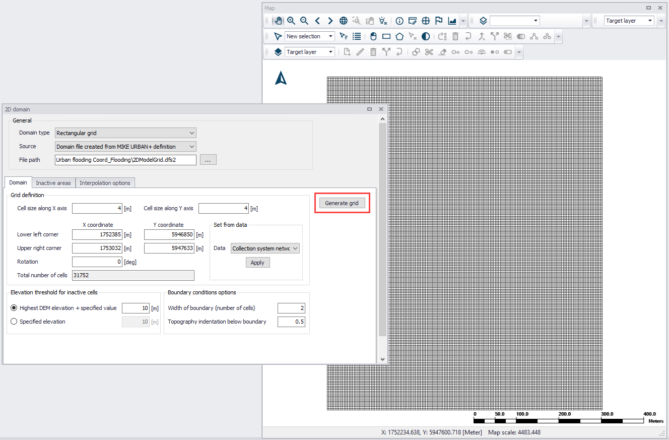
6. Examine the generated grid. Adjust grid sizes and extent, as needed. Re-generate the grid after changes to grid parameters.
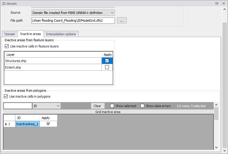
7. Define inactive areas, if any. If inactive areas shall be defined for the 2D domain, specify them as polygons on the Map, or load polygon feature layers that represent them into the project (see Chapter 3.1.3 for more details). Make sure to activate the appropriate tick boxes to apply the desired feature layers as inactive areas in the subsequent interpolation.
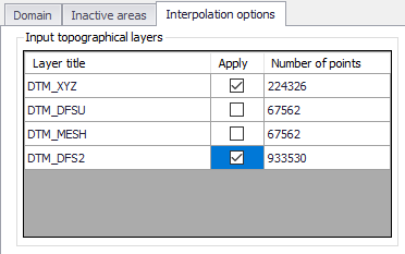
8. Configure interpolation parameters. Access the Interpolation Options tab page. Select the input topographical layers to use in the interpolation.
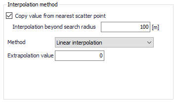
9. Choose the preferred interpolation method. More details on the methods are described in Chapter 3.1.4.
10. Click on the ‘Start interpolation’ button. A progress bar appears, and the status of the process is shown on the log window.

![]()