Creating a Flexible Mesh Workflow Example
1. Load desired input topographical layers to be used for 2D mesh value interpolation into the MIKE+ project.
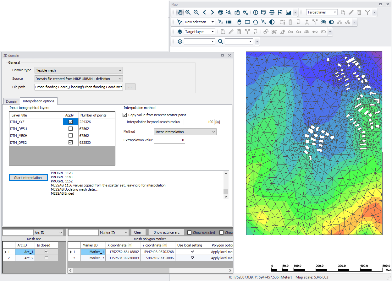
2. On the 2D Domain editor, choose a ‘Flexible mesh’ domain type and ‘Domain file created from MIKE+ definition’ as source. Specify the file name and path for the domain *.MESH file to be created.
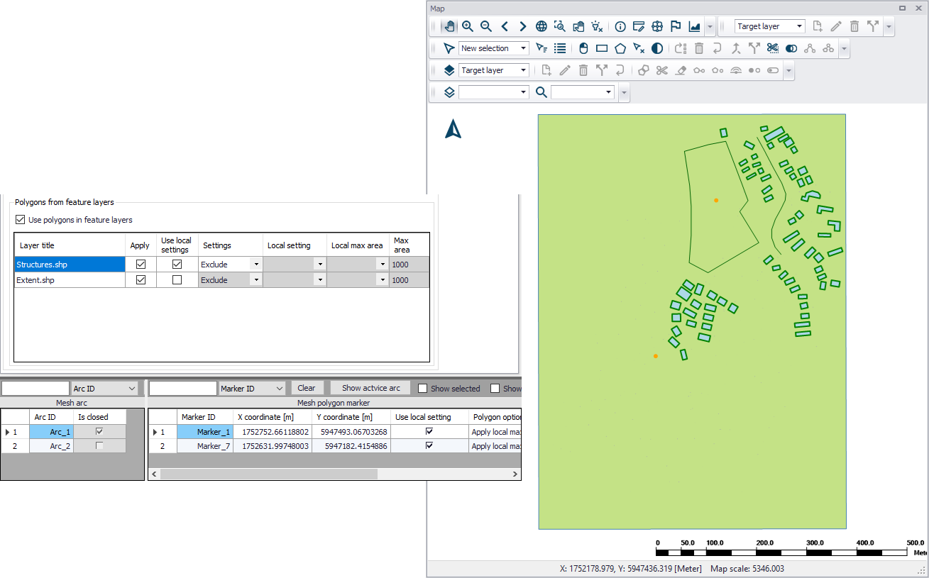
3. Configure mesh domain parameters. Define the mesh extent, and any local mesh areas via loaded polygon feature layers, or mesh arcs and polygons drawn directly on the Map. Pre-loaded feature layers are listed under the ‘Polygons from feature layers’ secondary table in the middle of the page, while arcs and polygons drawn on the Map are listed on the table at the bottom of the editor. More details on defining mesh areas are found in Chapter 3.1.2 - Flexible Mesh (p. 18).
4. Customize other meshing parameters on the Domain tab, such as ‘Maximum element area’ and ‘Smallest allowable angle’, if so desired. More details on these options are described in Chapter 3.1.2 - Flexible Mesh (p. 18).
5. Create a mesh by clicking on the ‘Generate mesh’ button on the Domain tab page or in the 2D overland tab in the ribbon.
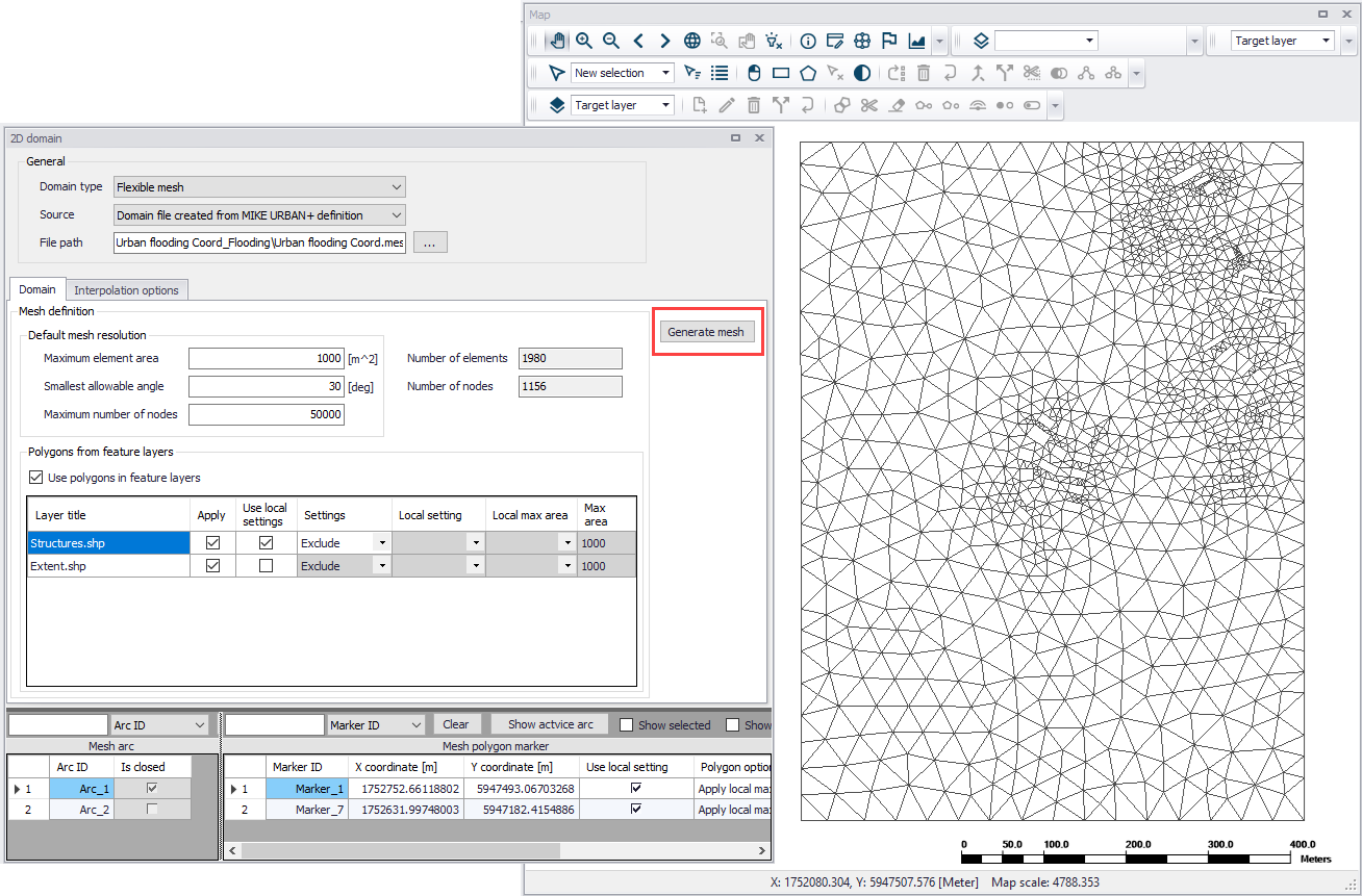
6. Examine the generated computational mesh. Adjust element sizes, the extent, or mesh areas using arcs and polygons, as needed. Re-generate the mesh after changes to meshing boundaries and parameters.
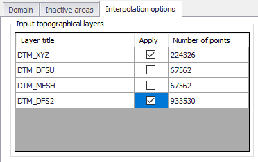
7. Configure interpolation parameters. When ready to finalize the 2D mesh, access the Interpolation Options tab page to begin interpolating topographical values onto the mesh. Select the input topographical layers to use in the interpolation.
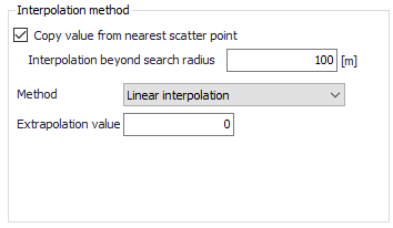
8. Choose the preferred interpolation method. More details on the methods are described in Chapter 3.1.4 - Interpolation Method (p. 26).
9. Click on the ‘Start interpolation’ button. A progress bar appears, and the status of the process is shown on the log window.
![]()