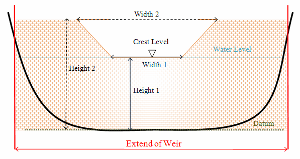
Weir data are defined in two grid tables in the present page:
Upper Input data grid and Lower Input data grid.

Figure 5.4 Setup definitions of contracted weir
The number of weirs must be defined initially. This number defines the number of structure definition lines which will be present for defining weir input data.
Name
Location
Type
Valve
Alpha zero
Head loss factors
The Name of weir is a user defined ID-string for each weir.

Note: Names must not be identical for different structures included in the model simulations.
'Location' and 'Projection' columns define the actual location of the weir.
Weirs are defined in the model area as a cross section specified as a list of points (a minimum of two points required), through which the structure flow occurs. The weir section is composed of a sequence of straight line segments between successive points, where the geographical coordinates are defined in the 'point selection' dialog which opens when pressing the  button in the 'Location' column. You must also select the map projection (Longitude/Latitude, UTM etc.) in which the specified location coordinates for the weir are defined.
See also Location of a structure (p. 125).
The weir-formula to be applied is selected from the drop down selection list in the 'Type' column. A range of formulas are available:
· Broad crested weir formula
· Weir formula 2 (Honma formula)
Valve regulation of the structure flow can be defined as part of the weir definition. Four different valve regulation types are available:
· None: No valve regulation applies (flow is not regulated).
· Only Positive Flow
Only flow in positive flow direction is allowed. Valve regulation does not allow flow in negative flow direction and the flow through the structure will be zero in this case.
· Only Negative Flow
Only flow in negative flow direction is allowed. Valve regulation does not allow flow in positive flow direction and the flow through the structure will be zero in this case.
· No Flow
No flow is allowed in the structure. Valve regulation closes completely the structure.
See also Flow directions for specific structure parameters.
When the water level gradient across a structure is small the corresponding gradient of the discharge with respect to the water levels is large. This in turn may result in a very rapid flow response to minor changes in the water level upstream and downstream. As a way of controlling this effect a Alpha Zero factor has been introduced. The Alpha Zero factor defines the water level difference below which the discharge gradients are suppressed. The default setting is 0.01 meter. If a structure shows oscillatory behaviour it is recommended to increase this value slightly.
The Loss Factors determines the energy (Head) loss of the flow over the weir. These are defined in the last six columns. Each loss factor is defined by a suffix, where '+' indicates Positive Flow direction and; suffix '-' indicates Negative Flow direction.(e.g. 'Inflow -' means inflow loss coefficient for negative flow direction).
Three types of Loss factors are present for both positive and negative flow direction:
· Inflow (contraction loss)
· Outflow (expansion loss)
· Free flow
Head Loss Factors are applied in structure flow calculation only for the broad crested weir type. See also Head Loss Factors (p. 128).
The lower input data grid contains the geometry definition for the broad crested weir type or alternatively values of weir formula parameters if one of the weir formulas have been selected.
For the Broad crested weir formula the geometrical shape of the active flow area must be defined by a Level-width relationship table. The levels are defined relative to the datum (starting from the crest or sill level and up). E.g. for a horizontal weir positioned at invert level -10m (bed level) and extending 6 m above the bed, the weir could should be defined by L0= -4m and L1= 0m. Datum defines an offset which is added to the level column in the level/width table during computation.
Pressing the  button in the 'Geometry' column opens a Level-Width dialog where the geometry relation can be entered. '
For Weir formula 1 and Weir formula 2 the geometry of the structure itself must be defined. From this the active flow area will be calculated automatically in the simulation. Values for the respective weir formula parameters must be defined in the respective columns.
See also Weirs (p. 126).