The Weirs page in MIKE 11 includes different types and formulas for overflow weirs. The weirs property page is presented in Figure 2.49.
Weir definitions comprise the following data.
Location
· River Name:
Name of the river branch in which the weir is located.
· Chainage:
Chainage at which the weir is located.
· ID:
String identification of the weir. ID will be used in structure results and hence makes it easier to identify a specific structure if a setup contains many structures, or if multiple structures are defined at the same location. It is recommended always to give the weir an ID.
· Type:
The location type may be Regular, Side Structure or Side Structure + Reservoir. See 2.3.3 Structure Types definition (p. 72) for details.
Attributes
· Type:
Type of Overflow Weir formulation:
· Broad Crested Weir:
Broad Crested weir formulation is used for calculating the Q/h relation table on the page which contains corresponding values for water level and discharge for critical flow conditions at the crest.
· Special Weir:
Special Weir is chosen in the situation where a Broad Crested weir formulation is not valid. For this weir type, the Q/h relationship table for free overflow must be specified manually by the user.
· Weir Formula 1:A standard weir expression reduced according to the Villemonte formula is applied. See the Reference Manual.
· Weir Formula 2 (Honma):
The Weir Formula 2 is the Honma weir expression.
See the Reference Manual.
· Weir Formula 3(Extended Honma):
An extended version of the Honma weir formula is applied in Weir Formula 3. See the Reference Manual.
· Valve:
· None:
No valve regulation applies.
· Only Positive Flow:
Only positive flow is allowed, i.e. whenever the water level downstream is higher than upstream the flow through the structure will be zero.
· Only Negative Flow:
Only negative flow is allowed, i.e. whenever the water level upstream is higher than downstream the flow through the structure will be zero.
The factors determining the energy loss occurring for flow through hydraulic structures (only active for broad crested weir and special weir).
· Geometry definitions applies only for broad crested weir and special weir types.
· Type of Geometry:
· Level-Width:
The weir geometry is specified as a level/width table relative to the datum.
· Cross Section DB:
The weir geometry is specified in the cross section editor. A cross section with a matching branch name, Topo ID and chainage must exist in the applied cross section file. The Topo ID is assumed to be the same as that specified in the Branches Property page, see Topo ID (p. 61).
· Datum:
Offset which is added to the level column in the level/width table.
· Level/Width table:
Weir shape defined as levels and corresponding flow widths. Values in the levels column must be increasing. See also section 2.3.4 Structure Geometry definition (p. 77).
Weir formula Parameters (only weir formula 1)
Width: Width of the flow.
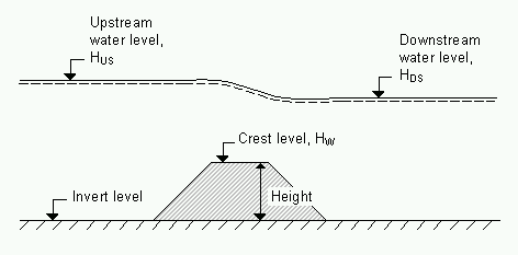
Height: Weir height. See Figure 2.52
Weir Coeff.: Multiplication coefficient in the weir formula.
Weir Exp.: Exponential coefficient in the weir formula.
Invert Level: Bottom datum level. See Figure 2.52
Weir formula 2 Parameters (only weir formula 2 (Honma))
Weir coefficient (C1): Multiplication coefficient in the Honma weir formula.
Weir width: Width of the flow.
Weir crest level: Weir level. See Figure 2.52
Figure 2.52 Definition sketch for Weir formula
Weir formula 3 Parameters (only weir formula 2 (Honma))
When choosing weir formula 3 a separate dialog can be opened by clicking the “Details...” button. See the following figure:
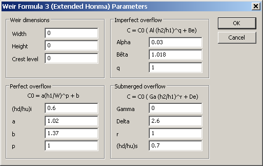
Figure 2.53 Parameter definition dialog for Weir formula 3
Using weir formula 3 several parameters are to be specified for calculation of the flow in three regimes: perfect, imperfect and submerged overflow. MIKE 11 does not check if there is a continuous transition from one flow regime to the next. This has to be ensured by the user through proper selection of the parameters.
Free Overflow Q/h-relations (only broad crested weir and special weir)
· Broad crested weir:
The Q/h relations are calculated using the Calculate button after all relevant information has been entered. The result of the calculation will appear in the table. In order to compute the Q/h relation, the nearest upstream and downstream cross section are used. The cross sections must be within the distance maximum dx (Maximum dx (p. 63)) defined for the branch in question. The Q/h relation can not be calculated unless the cross sections are defined. It is also necessary that the Simulation File is open in order to load the cross section data from a cross section file.
Table content are;
- Q : Structure Discharge
- H-Pos: Water Level upstream in case of Positive flow
- H-Neg: Water Level downstream in case of Negative flood
- H-Weir: Water Level at structure
- Width: Structure width for actual structure level
- Area: Structure Area for actual structure level
· Special weir:
Unlike for the broad crested weir, where Q/h relations are calculated automatically, the user must manually specify Q/h relations corresponding to free overflow conditions for a Special weir. These must be specified for both positive and negative flows.

Note that Q/h relations must be re-calculated if any changes are made to the weir or the cross sections up- or downstream have been altered. Further, since a weir in MIKE 11 is defined as a structure causing a contraction loss and subsequently an expansion loss, some constraints are placed on the geometry of a broad crested weir. The geometry of the weir must be such that the cross sectional area at the weir is less than the cross sectional area at both the upstream and the downstream cross section for all water levels!
![]()